ECD SYSTEM(for DPF), Diagnostic DTC:P042E
| DTC Code | DTC Name |
|---|---|
| P042E | Exhaust Gas Recirculation "A" Control Stuck Open |
DESCRIPTION
The EGR system recirculates exhaust gases. The recirculated gas mingles with the intake air so that the EGR system can slow combustion speed and keep the combustion temperature down. This helps reduce NOx emissions.
In order to increase EGR circulation efficiency, the ECM adjusts the EGR valve angle and the throttle valve angle.
DTC No. |
Detection Item |
DTC Detection Condition |
Trouble Area |
MIL |
Memory |
|---|---|---|---|---|---|
P042E |
Exhaust Gas Recirculation "A" Control Stuck Open |
|
|
Comes on |
DTC stored |
DTC No. |
Data List |
|---|---|
P042E |
|
Actual EGR valve opening percentage: Fully closed = 0%, fully open = 100%.
If DTC P042E is stored, the following symptoms may appear:
-
Stuck closed malfunction
-
Lack of power: due to fail-safe operation (only for vehicle with DPF catalyst)
Intake booming noise
Slight combustion noise
Stuck open malfunction
-
Black smoke
Lack of power
Vibration at engine stop
Misfire
White smoke
Engine stall
MONITOR DESCRIPTION
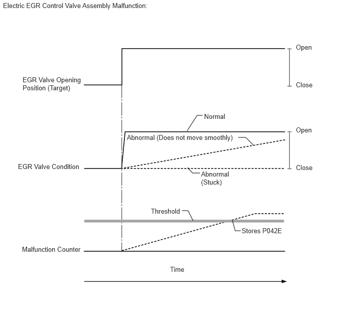
When the target and actual positions of the EGR valve are different, the ECM interprets this as a malfunction of the electric EGR control valve assembly and illuminates the MIL (1 trip detection logic).
If a large amount of carbon deposits exists in the electric EGR control valve assembly, the following parts possibly also have deposits inside: The intake manifold, EGR cooler assembly, exhaust fuel addition injector assembly (if equipped), DPF catalyst, and other parts related to the exhaust gas.
Be sure to carefully examine "Actual EGR Valve Pos.", "Target EGR Position" and "MAF" in the freeze frame data.
CONFIRMATION DRIVING PATTERN
DTC No. |
DTC Detection Drive Pattern |
|---|---|
P042E |
After warming up engine and idling for 60 seconds, maintain engine speed at 2500 rpm for 40 seconds, drive vehicle, and perform engine brake deceleration by fully closing accelerator when engine speed is 2000 rpm or more. |
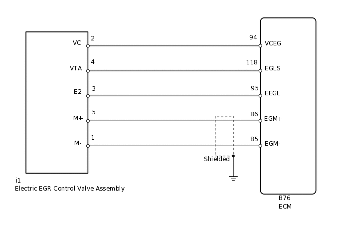
WIRING DIAGRAM
CAUTION / NOTICE / HINT
After replacing the ECM, the new ECM needs registration (Click here) and initialization (Click here).
Read freeze frame data using the GTS. Freeze frame data records the engine condition when malfunctions are detected. When troubleshooting, freeze frame data can help determine if the vehicle was moving or stationary, if the engine was warmed up or not, and other data from the time the malfunction occurred.
PROCEDURE
CHECK ANY OTHER DTCS OUTPUT (IN ADDITION TO DTC P042E)
Connect the GTS to the DLC3.
Turn the ignition switch to ON.
Turn the GTS on.
Enter the following menus: Powertrain / Engine and ECT / Trouble Codes.
Powertrain > Engine > Trouble Codes
Read the DTCs.
Result
Proceed to
P042E is output
P042E and other DTCs are output
Tip:If any DTCs other than P042E are output, troubleshoot those DTCs first.
PERFORM ACTIVE TEST USING GTS (CONTROL THE EGR STEP POSITION)
Connect the GTS to the DLC3.
Turn the ignition switch to ON.
Turn the GTS on.
Enter the following menus: Powertrain / Engine and ECT / Active Test / Control the EGR Step Position / Data List / Target EGR Position and Actual EGR Valve Pos.
Powertrain > Engine > Active Test
Active Test Display
Control the EGR Step Position
Data List Display
Target EGR Position
Actual EGR Valve Pos.
When changing the Active Test value for 1, 25, 50, 75 and 100%, check that Actual EGR Valve Pos. smoothly changes to the set opening angle.
OK
The Actual EGR Valve Pos. value follows the Target EGR Position value.
Result
Proceed to
OK
NG
NG REPLACE ELECTRIC EGR CONTROL VALVE ASSEMBLYClick here
PERFORM ACTIVE TEST USING GTS (CONTROL THE EGR STEP POSITION)
Remove the electric EGR control valve assembly.
Reconnect the electric EGR control valve assembly connector.
Connect the GTS to the DLC3.
Turn the ignition switch to ON.
Turn the GTS on.
Enter the following menus: Powertrain / Engine and ECT / Active Test / Control the EGR Step Position.
Powertrain > Engine > Active Test
Tester Display
Control the EGR Step Position
Check if the valve of the electric EGR control valve assembly opens/closes when an Active Test is performed.
OK
The valve opens/closes.
-
*a
OK
*b
NG
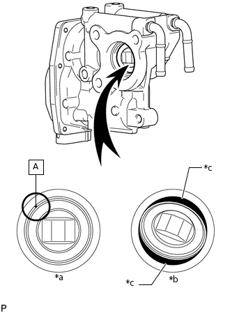
*c
Gap
Hold the electric EGR control valve assembly up to a light, and then from the side indicated by the arrow in the illustration, visually check that there is no gap between the valve and body.
OK
No light passes through (there is no gap between the valve and body).
Result
Result
Proceed to
NG
A
OK
B
Tip:If light passes through (there is a gap between the valve and body), replace the electric EGR control valve assembly.
Light passes through part A shown in the illustration even if the valve is completely closed. This is not a problem.
Remove the deposits if there are many deposits in the electric EGR control valve assembly or the passage of the intake manifold.
B CHECK FOR DEPOSITClick here
REPLACE ELECTRIC EGR CONTROL VALVE ASSEMBLY
Replace the electric EGR control valve assembly.
Tip:Before replacing the electric EGR control valve assembly, check the connections of the wire harness and connectors. If there is any abnormality, replace or repair the wire harness or connector.
Result
Proceed to
NEXT
NEXT CONFIRM WHETHER MALFUNCTION HAS BEEN SUCCESSFULLY REPAIREDClick here
CHECK FOR DEPOSIT
Remove the electric EGR control valve assembly.
Visually check the electric EGR control valve assembly for deposits. If there are deposits, clean the electric EGR control valve assembly.
Note:When cleaning the electric EGR control valve, make sure the valve is completely closed.
Do not forcibly open the valve, as it may be damaged or deformed.
When cleaning the electric EGR control valve, use a piece of cloth soaked with cleaning solvent. Spraying the solvent directly onto these parts or soaking the parts in the solvent may damage the parts.
When cleaning the EGR control valve, care should be taken to prevent the ingress of cleaning solvent into the bearings of valve shaft, and when wiping off deposits on the EGR control valve, care should be taken not to push the deposits into the bearings of valve shaft. These contaminants may adversely affect on the function of EGR control valve.
Tip:If the EGR valve does not open properly or is stuck closed, the amount of intake air increases and combustion sounds and engine vibration may increase.
If the EGR valve does not close properly or is stuck open, EGR becomes excessive and combustion becomes unstable. Also, there may be a lack of power.
Reinstall the electric EGR control valve assembly.
Result
Proceed to
NEXT
CONFIRM WHETHER MALFUNCTION HAS BEEN SUCCESSFULLY REPAIRED
Connect the GTS to the DLC3.
Turn the ignition switch to ON.
Turn the GTS on.
Clear the DTCs.
Powertrain > Engine > Clear DTCs
Turn the ignition switch off and wait for 30 seconds or more.
Turn the ignition switch to ON and turn the GTS on.
After warming up engine and idling for 60 seconds, maintain engine speed at 2500 rpm for 40 seconds, drive vehicle, and perform engine brake deceleration by fully closing accelerator when engine speed is 2000 rpm or higher.
CAUTION:When performing the confirmation driving pattern, obey all speed limits and traffic laws.
Enter the following menus: Powertrain / Engine and ECT / Trouble Codes.
Powertrain > Engine > Trouble Codes
Confirm that the DTC is not output again.
Result
Proceed to
NEXT
NEXT END