AIRBAG SYSTEM, Diagnostic DTC:B1695/16
| DTC Code | DTC Name |
|---|---|
| B1695/16 | Door Side Airbag Sensor LH Malfunction |
DESCRIPTION
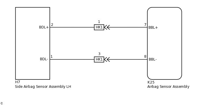
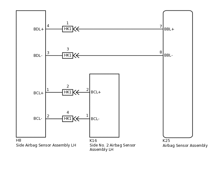
The side collision sensor LH circuit (to determine deployment of the front seat airbag assembly LH, curtain shield airbag assembly LH* and front seat outer belt assembly LH) consists of the airbag sensor assembly, side airbag sensor assembly LH and side No. 2 airbag sensor assembly LH*.
The side airbag sensor assembly LH and side No. 2 airbag sensor assembly LH* detect impacts to the vehicle and send signals to the airbag sensor assembly to determine if the airbags and pretensioner should be deployed.
DTC B1695/16 is stored when a malfunction is detected in the side collision sensor LH circuit.
DTC No. |
Detection Item |
DTC Detection Condition |
Trouble Area |
Test Mode / Check Mode |
|---|---|---|---|---|
B1695/16 |
Door Side Airbag Sensor LH Malfunction |
|
|
Does not apply to test/check mode |
*: w/ Curtain Shield Airbags
WIRING DIAGRAM
w/o Curtain Shield Airbags:
w/ Curtain Shield Airbags:
CAUTION / NOTICE / HINT
After turning the ignition switch off, waiting time may be required before disconnecting the cable from the negative (-) battery terminal. Therefore, make sure to read the disconnecting the cable from the negative (-) battery terminal notices before proceeding with work.
PROCEDURE
CHECK VEHICLE CONDITION
Choose the model to be inspected.
Result
Result
Proceed to
w/o Curtain Shield Airbags
A
w/ Curtain Shield Airbags
B
B CHECK CONNECTORSClick here
CHECK CONNECTORS
Turn the ignition switch off.
Disconnect the cable from the negative (-) battery terminal.
CAUTION:Wait at least 90 seconds after disconnecting the cable from the negative (-) battery terminal to disable the SRS system.
Check that the connectors are properly connected to the airbag sensor assembly and side airbag sensor assembly LH. Also check that the connectors that link the front door wire LH and floor wire are properly connected.
OK
The connectors are properly connected.
Tip:If the connectors are not properly connected, reconnect the connectors and proceed to the next inspection.
Disconnect the connectors from the airbag sensor assembly and side airbag sensor assembly LH. Also disconnect the connectors that link the front door wire LH and floor wire.
Check that the terminals of the connectors are not damaged.
OK
The terminals are not deformed or damaged.
Result
Proceed to
OK
NG
NG REPLACE WIRE HARNESS
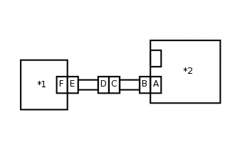
CHECK WIRE HARNESS (OPEN)
-
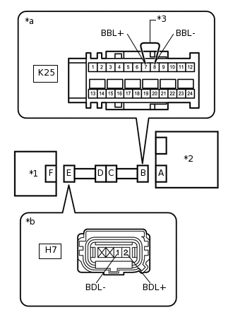
*1
Side Airbag Sensor Assembly LH
*2
Airbag Sensor Assembly
*3
Service Wire
*a
Front view of wire harness connector
(to Airbag Sensor Assembly)
*b
Front view of wire harness connector
(to Side Airbag Sensor Assembly LH)
Connect the connectors that link the front door wire LH and floor wire.
Using a service wire, connect terminals 7 (BBL+) and 8 (BBL-) of connector B.
Note:Do not forcibly insert the service wire into the terminals of the connector when connecting the wire.
Measure the resistance according to the value(s) in the table below.
Standard Resistance
Tester Connection
Condition
Specified Condition
H7-2 (BDL+) - H7-1 (BDL-)
Always
Below 1 Ω
Result
Proceed to
OK
NG
NG CHECK FLOOR WIRE (OPEN)Click here
-
CHECK WIRE HARNESS (SHORT)
-
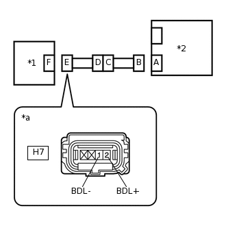
*1
Side Airbag Sensor Assembly LH
*2
Airbag Sensor Assembly
*a
Front view of wire harness connector
(to Side Airbag Sensor Assembly LH)
Disconnect the service wire from connector B.
Measure the resistance according to the value(s) in the table below.
Standard Resistance
Tester Connection
Condition
Specified Condition
H7-2 (BDL+) - H7-1 (BDL-)
Always
1 MΩ or higher
Result
Proceed to
OK
NG
NG CHECK FLOOR WIRE (SHORT)Click here
-
CHECK WIRE HARNESS (SHORT TO B+)
-
*1
Side Airbag Sensor Assembly LH
*2
Airbag Sensor Assembly
*a
Front view of wire harness connector
(to Side Airbag Sensor Assembly LH)
Connect the cable to the negative (-) battery terminal.
Turn the ignition switch to ON.
Measure the voltage according to the value(s) in the table below.
Standard Voltage
Tester Connection
Condition
Specified Condition
H7-2 (BDL+) - Body ground
Ignition switch ON
Below 1 V
H7-1 (BDL-) - Body ground
Ignition switch ON
Below 1 V
Turn the ignition switch off.
Disconnect the cable from the negative (-) battery terminal.
CAUTION:Wait at least 90 seconds after disconnecting the cable from the negative (-) battery terminal to disable the SRS system.
Result
Proceed to
OK
NG
NG CHECK FLOOR WIRE (SHORT TO B+)Click here
-
CHECK WIRE HARNESS (SHORT TO GROUND)
-
*1
Side Airbag Sensor Assembly LH
*2
Airbag Sensor Assembly
*a
Front view of wire harness connector
(to Side Airbag Sensor Assembly LH)
Measure the resistance according to the value(s) in the table below.
Standard Resistance
Tester Connection
Condition
Specified Condition
H7-2 (BDL+) - Body ground
Always
1 MΩ or higher
H7-1 (BDL-) - Body ground
Always
1 MΩ or higher
Result
Proceed to
OK
NG
NG CHECK FLOOR WIRE (SHORT TO GROUND)Click here
-
CHECK SIDE AIRBAG SENSOR ASSEMBLY LH
-
*1
Side Airbag Sensor Assembly RH
*2
Airbag Sensor Assembly
Connect the connectors to the airbag sensor assembly.
Interchange the side airbag sensor assembly LH with RH and connect the connectors.
Connect the cable to the negative (-) battery terminal.
Clear the DTCs stored in memory.
Body Electrical > SRS Airbag > Clear DTCs
Turn the ignition switch off.
Turn the ignition switch to ON, and wait for at least 60 seconds.
Check for DTCs.
Body Electrical > SRS Airbag > Trouble Codes
Tip:Codes other than DTCs B1690/15 and B1695/16 may be output at this time, but they are not related to this check.
Turn the ignition switch off.
Disconnect the cable from the negative (-) battery terminal.
CAUTION:Wait at least 90 seconds after disconnecting the cable from the negative (-) battery terminal to disable the SRS system.
Return the side airbag sensor assembly LH and RH to their original positions and connect the connectors.
Result
Result
Proceed to
DTC B1695/16 is output.
A
DTC B1690/15 is output.
B
DTCs B1690/15 and B1695/16 are not output.
C
-
CHECK FLOOR WIRE (SHORT TO GROUND)
-
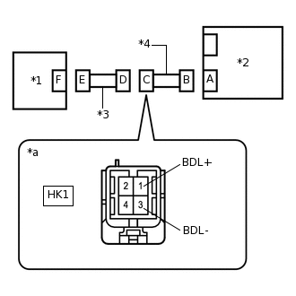
*1
Side Airbag Sensor Assembly LH
*2
Airbag Sensor Assembly
*3
Front Door Wire LH
*4
Floor Wire
*a
Front view of wire harness connector
(to Front Door Wire LH)
Disconnect the floor wire connector from the front door wire LH.
Measure the resistance according to the value(s) in the table below.
Standard Resistance
Tester Connection
Condition
Specified Condition
HK1-1 (BDL+) - Body ground
Always
1 MΩ or higher
HK1-3 (BDL-) - Body ground
Always
1 MΩ or higher
Result
Proceed to
OK
NG
OK REPLACE FRONT DOOR WIRE LH
NG REPLACE FLOOR WIRE
-
CHECK FLOOR WIRE (SHORT TO B+)
-
*1
Side Airbag Sensor Assembly LH
*2
Airbag Sensor Assembly
*3
Front Door Wire LH
*4
Floor Wire
*a
Front view of wire harness connector
(to Front Door Wire LH)
Disconnect the floor wire connector from the front door wire LH.
Connect the cable to the negative (-) battery terminal.
Turn the ignition switch to ON.
Measure the voltage according to the value(s) in the table below.
Standard Voltage
Tester Connection
Condition
Specified Condition
HK1-1 (BDL+) - Body ground
Ignition switch ON
Below 1 V
HK1-3 (BDL-) - Body ground
Ignition switch ON
Below 1 V
Result
Proceed to
OK
NG
OK REPLACE FRONT DOOR WIRE LH
NG REPLACE FLOOR WIRE
-
CHECK FLOOR WIRE (SHORT)
-
*1
Side Airbag Sensor Assembly LH
*2
Airbag Sensor Assembly
*3
Front Door Wire LH
*4
Floor Wire
*a
Front view of wire harness connector
(to Front Door Wire LH)
Disconnect the floor wire connector from the front door wire LH.
Measure the resistance according to the value(s) in the table below.
Standard Resistance
Tester Connection
Condition
Specified Condition
HK1-1 (BDL+) - HK1-3 (BDL-)
Always
1 MΩ or higher
Result
Proceed to
OK
NG
OK REPLACE FRONT DOOR WIRE LH
NG REPLACE FLOOR WIRE
-
CHECK FLOOR WIRE (OPEN)
-
*1
Side Airbag Sensor Assembly LH
*2
Airbag Sensor Assembly
*3
Front Door Wire LH
*4
Floor Wire
*5
Service Wire
*a
Front view of wire harness connector
(to Airbag Sensor Assembly)
*b
Front view of wire harness connector
(to Front Door Wire LH)
Disconnect the floor wire connector from the front door wire LH.
Tip:The service wire has already been inserted into connector B.
Measure the resistance according to the value(s) in the table below.
Standard Resistance
Tester Connection
Condition
Specified Condition
HK1-1 (BDL+) - HK1-3 (BDL-)
Always
Below 1 Ω
Disconnect the service wire from connector B.
Result
Proceed to
OK
NG
OK REPLACE FRONT DOOR WIRE LH
NG REPLACE FLOOR WIRE
-
CHECK CONNECTORS
Turn the ignition switch off.
Disconnect the cable from the negative (-) battery terminal.
CAUTION:Wait at least 90 seconds after disconnecting the cable from the negative (-) battery terminal to disable the SRS system.
Check that the connectors are properly connected to the airbag sensor assembly, side airbag sensor assembly LH and side No. 2 airbag sensor assembly LH. Also check that the connectors that link the front door wire LH and floor wire are properly connected.
OK
The connectors are properly connected.
Tip:If the connectors are not properly connected, reconnect the connectors and proceed to the next inspection.
Disconnect the connectors from the airbag sensor assembly, side airbag sensor assembly LH and side No. 2 airbag sensor assembly LH. Also disconnect the connectors that link the front door wire LH and floor wire.
Check that the terminals of the connectors are not damaged.
OK
The terminals are not deformed or damaged.
Result
Proceed to
OK
NG
NG REPLACE WIRE HARNESS
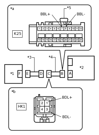
CHECK WIRE HARNESS (OPEN)
-
*1
Side Airbag Sensor Assembly LH
*2
Airbag Sensor Assembly
*3
Service Wire
*a
Front view of wire harness connector
(to Airbag Sensor Assembly)
*b
Front view of wire harness connector
(to Side Airbag Sensor Assembly LH)
Connect the connectors that link the front door wire LH and floor wire.
Using a service wire, connect terminals 7 (BBL+) and 8 (BBL-) of connector B.
Note:Do not forcibly insert the service wire into the terminals of the connector when connecting the wire.
Measure the resistance according to the value(s) in the table below.
Standard Resistance
Tester Connection
Condition
Specified Condition
H8-4 (BDL+) - H8-3 (BDL-)
Always
Below 1 Ω
Result
Proceed to
OK
NG
NG CHECK FLOOR WIRE (OPEN)Click here
-
CHECK WIRE HARNESS (SHORT)
-
*1
Side Airbag Sensor Assembly LH
*2
Airbag Sensor Assembly
*a
Front view of wire harness connector
(to Side Airbag Sensor Assembly LH)
Disconnect the service wire from connector B.
Measure the resistance according to the value(s) in the table below.
Standard Resistance
Tester Connection
Condition
Specified Condition
H8-4 (BDL+) - H8-3 (BDL-)
Always
1 MΩ or higher
Result
Proceed to
OK
NG
NG CHECK FLOOR WIRE (SHORT)Click here
-
CHECK WIRE HARNESS (SHORT TO B+)
-
*1
Side Airbag Sensor Assembly LH
*2
Airbag Sensor Assembly
*a
Front view of wire harness connector
(to Side Airbag Sensor Assembly LH)
Connect the cable to the negative (-) battery terminal.
Turn the ignition switch to ON.
Measure the voltage according to the value(s) in the table below.
Standard Voltage
Tester Connection
Condition
Specified Condition
H8-4 (BDL+) - Body ground
Ignition switch ON
Below 1 V
H8-3 (BDL-) - Body ground
Ignition switch ON
Below 1 V
Turn the ignition switch off.
Disconnect the cable from the negative (-) battery terminal.
CAUTION:Wait at least 90 seconds after disconnecting the cable from the negative (-) battery terminal to disable the SRS system.
Result
Proceed to
OK
NG
NG CHECK FLOOR WIRE (SHORT TO B+)Click here
-
CHECK WIRE HARNESS (SHORT TO GROUND)
-
*1
Side Airbag Sensor Assembly LH
*2
Airbag Sensor Assembly
*a
Front view of wire harness connector
(to Side Airbag Sensor Assembly LH)
Measure the resistance according to the value(s) in the table below.
Standard Resistance
Tester Connection
Condition
Specified Condition
H8-4 (BDL+) - Body ground
Always
1 MΩ or higher
H8-3 (BDL-) - Body ground
Always
1 MΩ or higher
Result
Proceed to
OK
NG
NG CHECK FLOOR WIRE (SHORT TO GROUND)Click here
-
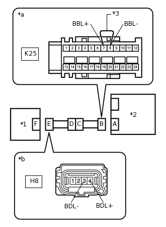
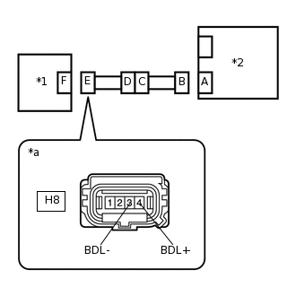
CHECK WIRE HARNESS (OPEN)
-
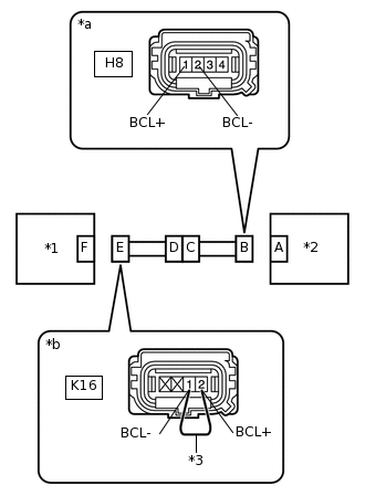
*1
Side No. 2 Airbag Sensor Assembly LH
*2
Side Airbag Sensor Assembly LH
*3
Service Wire
*a
Front view of wire harness connector
(to Side Airbag Sensor Assembly LH)
*b
Front view of wire harness connector
(to Side No. 2 Airbag Sensor Assembly LH)
Using a service wire, connect terminals 2 (BCL+) and 1 (BCL-) of connector E.
Note:Do not forcibly insert the service wire into the terminals of the connector when connecting the wire.
Measure the resistance according to the value(s) in the table below.
Standard Resistance
Tester Connection
Condition
Specified Condition
H8-1 (BCL+) - H8-2 (BCL-)
Always
Below 1 Ω
Result
Proceed to
OK
NG
NG CHECK FLOOR WIRE (OPEN)Click here
-
CHECK WIRE HARNESS (SHORT)
-
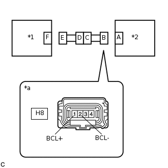
*1
Side No. 2 Airbag Sensor Assembly LH
*2
Side Airbag Sensor Assembly LH
*a
Front view of wire harness connector
(to Side Airbag Sensor Assembly LH)
Disconnect the service wire from connector E.
Measure the resistance according to the value(s) in the table below.
Standard Resistance
Tester Connection
Condition
Specified Condition
H8-1 (BCL+) - H8-2 (BCL-)
Always
1 MΩ or higher
Result
Proceed to
OK
NG
NG CHECK FLOOR WIRE (SHORT)Click here
-
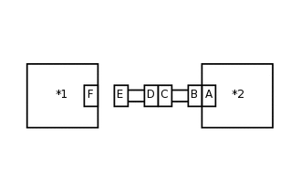
CHECK WIRE HARNESS (SHORT TO B+)
-
*1
Side No. 2 Airbag Sensor Assembly LH
*2
Side Airbag Sensor Assembly LH
*a
Front view of wire harness connector
(to Side Airbag Sensor Assembly LH)
Connect the cable to the negative (-) battery terminal.
Turn the ignition switch to ON.
Measure the voltage according to the value(s) in the table below.
Standard Voltage
Tester Connection
Condition
Specified Condition
H8-1 (BCL+) - Body ground
Ignition switch ON
Below 1 V
H8-2 (BCL-) - Body ground
Ignition switch ON
Below 1 V
Turn the ignition switch off.
Disconnect the cable from the negative (-) battery terminal.
CAUTION:Wait at least 90 seconds after disconnecting the cable from the negative (-) battery terminal to disable the SRS system.
Result
Proceed to
OK
NG
NG CHECK FLOOR WIRE (SHORT TO B+)Click here
-
CHECK WIRE HARNESS (SHORT TO GROUND)
-
*1
Side No. 2 Airbag Sensor Assembly LH
*2
Side Airbag Sensor Assembly LH
*a
Front view of wire harness connector
(to Side Airbag Sensor Assembly LH)
Measure the resistance according to the value(s) in the table below.
Standard Resistance
Tester Connection
Condition
Specified Condition
H8-1 (BCL+) - Body ground
Always
1 MΩ or higher
H8-2 (BCL-) - Body ground
Always
1 MΩ or higher
Result
Proceed to
OK
NG
NG CHECK FLOOR WIRE (SHORT TO GROUND)Click here
-
CHECK SIDE AIRBAG SENSOR ASSEMBLY LH
-
*1
Side Airbag Sensor Assembly RH
*2
Airbag Sensor Assembly
Connect the connectors to the airbag sensor assembly and side No. 2 airbag sensor assembly LH.
Interchange the side airbag sensor assembly LH with RH and connect the connectors.
Connect the cable to the negative (-) battery terminal.
Clear the DTCs stored in memory.
Body Electrical > SRS Airbag > Clear DTCs
Turn the ignition switch off.
Turn the ignition switch to ON, and wait for at least 60 seconds.
Check for DTCs.
Body Electrical > SRS Airbag > Trouble Codes
Tip:Codes other than DTCs B1690/15 and B1695/16 may be output at this time, but they are not related to this check.
Turn the ignition switch off.
Disconnect the cable from the negative (-) battery terminal.
CAUTION:Wait at least 90 seconds after disconnecting the cable from the negative (-) battery terminal to disable the SRS system.
Return the side airbag sensor assembly LH and RH to their original positions and connect the connectors.
Result
Result
Proceed to
DTC B1695/16 is output.
A
DTC B1690/15 is output.
B
DTCs B1690/15 and B1695/16 are not output.
C
-
CHECK SIDE NO. 2 AIRBAG SENSOR ASSEMBLY LH
-
*1
Side No. 2 Airbag Sensor Assembly LH
*2
Side Airbag Sensor Assembly LH
Disconnect the connector from the side No. 2 airbag sensor assembly LH.
Connect the cable to the negative (-) battery terminal.
Clear the DTCs stored in memory.
Body Electrical > SRS Airbag > Clear DTCs
Turn the ignition switch off.
Turn the ignition switch to ON, and wait for at least 60 seconds.
Check for DTCs.
Body Electrical > SRS Airbag > Trouble Codes
OK
DTC B1695/16 is not output.
Tip:Codes other than DTC B1695/16 may be output at this time, but they are not related to this check.
Result
Proceed to
OK
NG
-
CHECK FLOOR WIRE (SHORT TO GROUND)
-
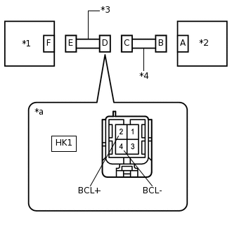
*1
Side No. 2 Airbag Sensor Assembly LH
*2
Side Airbag Sensor Assembly LH
*3
Floor Wire
*4
Front Door Wire LH
*a
Front view of wire harness connector
(to Front Door Wire LH)
Disconnect the floor wire connector from the front door wire LH.
Measure the resistance according to the value(s) in the table below.
Standard Resistance
Tester Connection
Condition
Specified Condition
HK1-2 (BCL+) - Body ground
Always
1 MΩ or higher
HK1-4 (BCL-) - Body ground
Always
1 MΩ or higher
Result
Proceed to
OK
NG
OK REPLACE FRONT DOOR WIRE LH
NG REPLACE FLOOR WIRE
-
CHECK FLOOR WIRE (SHORT TO B+)
-
*1
Side No. 2 Airbag Sensor Assembly LH
*2
Side Airbag Sensor Assembly LH
*3
Floor Wire
*4
Front Door Wire LH
*a
Front view of wire harness connector
(to Front Door Wire LH)
Disconnect the floor wire connector from the front door wire LH.
Connect the cable to the negative (-) battery terminal.
Turn the ignition switch to ON.
Measure the voltage according to the value(s) in the table below.
Standard Voltage
Tester Connection
Condition
Specified Condition
HK1-2 (BCL+) - Body ground
Ignition switch ON
Below 1 V
HK1-4 (BCL-) - Body ground
Ignition switch ON
Below 1 V
Result
Proceed to
OK
NG
OK REPLACE FRONT DOOR WIRE LH
NG REPLACE FLOOR WIRE
-
CHECK FLOOR WIRE (SHORT)
-
*1
Side No. 2 Airbag Sensor Assembly LH
*2
Side Airbag Sensor Assembly LH
*3
Floor Wire
*4
Front Door Wire LH
*a
Front view of wire harness connector
(to Front Door Wire LH)
Disconnect the floor wire connector from the front door wire LH.
Measure the resistance according to the value(s) in the table below.
Standard Resistance
Tester Connection
Condition
Specified Condition
HK1-2 (BCL+) - HK1-4 (BCL-)
Always
1 MΩ or higher
Result
Proceed to
OK
NG
OK REPLACE FRONT DOOR WIRE LH
NG REPLACE FLOOR WIRE
-
CHECK FLOOR WIRE (OPEN)
-
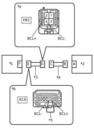
*1
Side No. 2 Airbag Sensor Assembly LH
*2
Side Airbag Sensor Assembly LH
*3
Floor Wire
*4
Front Door Wire LH
*5
Service Wire
*a
Front view of wire harness connector
(to Front Door Wire LH)
*b
Front view of wire harness connector
(to Side No. 2 Airbag Sensor Assembly LH)
Disconnect the floor wire connector from the front door wire LH.
Tip:The service wire has already been inserted into connector E.
Measure the resistance according to the value(s) in the table below.
Standard Resistance
Tester Connection
Condition
Specified Condition
HK1-2 (BCL+) - HK1-4 (BCL-)
Always
Below 1 Ω
Disconnect the service wire from connector E.
Result
Proceed to
OK
NG
OK REPLACE FRONT DOOR WIRE LH
NG REPLACE FLOOR WIRE
-
CHECK FLOOR WIRE (SHORT TO GROUND)
-
*1
Side Airbag Sensor Assembly LH
*2
Airbag Sensor Assembly
*3
Front Door Wire LH
*4
Floor Wire
*a
Front view of wire harness connector
(to Front Door Wire LH)
Disconnect the floor wire connector from the front door wire LH.
Measure the resistance according to the value(s) in the table below.
Standard Resistance
Tester Connection
Condition
Specified Condition
HK1-1 (BDL+) - Body ground
Always
1 MΩ or higher
HK1-3 (BDL-) - Body ground
Always
1 MΩ or higher
Result
Proceed to
OK
NG
OK REPLACE FRONT DOOR WIRE LH
NG REPLACE FLOOR WIRE
-
CHECK FLOOR WIRE (SHORT TO B+)
-
*1
Side Airbag Sensor Assembly LH
*2
Airbag Sensor Assembly
*3
Front Door Wire LH
*4
Floor Wire
*a
Front view of wire harness connector
(to Front Door Wire LH)
Disconnect the floor wire connector from the front door wire LH.
Connect the cable to the negative (-) battery terminal.
Turn the ignition switch to ON.
Measure the voltage according to the value(s) in the table below.
Standard Voltage
Tester Connection
Condition
Specified Condition
HK1-1 (BDL+) - Body ground
Ignition switch ON
Below 1 V
HK1-3 (BDL-) - Body ground
Ignition switch ON
Below 1 V
Result
Proceed to
OK
NG
OK REPLACE FRONT DOOR WIRE LH
NG REPLACE FLOOR WIRE
-
CHECK FLOOR WIRE (SHORT)
-
*1
Side Airbag Sensor Assembly LH
*2
Airbag Sensor Assembly
*3
Front Door Wire LH
*4
Floor Wire
*a
Front view of wire harness connector
(to Front Door Wire LH)
Disconnect the floor wire connector from the front door wire LH.
Measure the resistance according to the value(s) in the table below.
Standard Resistance
Tester Connection
Condition
Specified Condition
HK1-1 (BDL+) - HK1-3 (BDL-)
Always
1 MΩ or higher
Result
Proceed to
OK
NG
OK REPLACE FRONT DOOR WIRE LH
NG REPLACE FLOOR WIRE
-
CHECK FLOOR WIRE (OPEN)
-
*1
Side Airbag Sensor Assembly LH
*2
Airbag Sensor Assembly
*3
Front Door Wire LH
*4
Floor Wire
*5
Service Wire
*a
Front view of wire harness connector
(to Airbag Sensor Assembly)
*b
Front view of wire harness connector
(to Front Door Wire LH)
Disconnect the floor wire connector from the front door wire LH.
Tip:The service wire has already been inserted into connector B.
Measure the resistance according to the value(s) in the table below.
Standard Resistance
Tester Connection
Condition
Specified Condition
HK1-1 (BDL+) - HK1-3 (BDL-)
Always
Below 1 Ω
Disconnect the service wire from connector B.
Result
Proceed to
OK
NG
OK REPLACE FRONT DOOR WIRE LH
NG REPLACE FLOOR WIRE
-