AIR CONDITIONING SYSTEM Steering Pad Switch Circuit
DESCRIPTION
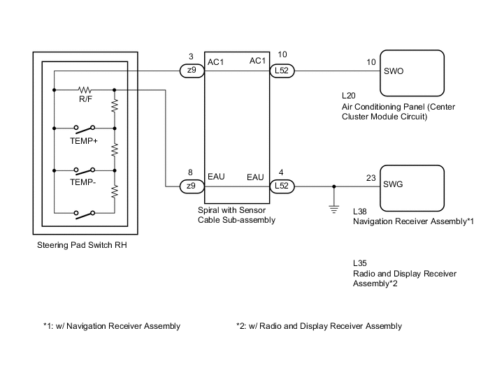
The temperature can be adjusted and the air inlet can be switched between fresh air mode and recirculated mode by operating switches on the steering pad switch RH. The air conditioning panel (center cluster module circuit) receives operation signals from the steering pad switch RH via the spiral with sensor cable sub-assembly and sends temperature setting and air inlet change signals to the air conditioning amplifier assembly.
WIRING DIAGRAM
PROCEDURE
-
INSPECT AIR CONDITIONING PANEL (CENTER CLUSTER MODULE CIRCUIT)
-
Disconnect the L52 spiral with sensor cable sub-assembly connector.
-
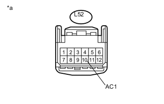
Text in Illustration *a Front view of wire harness connector
(to Spiral with Sensor Cable Sub-assembly)
Measure the voltage according to the value(s) in the table below.
Standard Voltage Tester Connection Condition Specified Condition L52-10 (AC1) - Body ground Power switch off Below 1 V L52-10 (AC1) - Body ground Power switch on (IG) 4.5 to 5.5 V
NG 
CHECK HARNESS AND CONNECTOR (CENTER CLUSTER MODULE CIRCUIT - SPIRAL WITH SENSOR CABLE SUB-ASSEMBLY) Click here
OK 
-
-
CHECK HARNESS AND CONNECTOR (SPIRAL WITH SENSOR CABLE SUB-ASSEMBLY - BODY GROUND)
-
Disconnect the L38 navigation receiver assembly connector*1.
-
Disconnect the L35 radio and display receiver assembly connector*2.
-
Measure the resistance according to the value(s) in the table below.
Standard Resistance Tester Connection Condition Specified Condition L52-4 (EAU) - L38-23 (SWG)*1 Always Below 1 Ω L52-4 (EAU) - L35-23 (SWG)*2 Always Below 1 Ω L52-4 (EAU) - Body ground Always 10 kΩ or higher
-
*1: w/ Navigation Receiver Assembly
-
*2: w/ Radio and Display Receiver Assembly
-
NG 
REPAIR OR REPLACE HARNESS OR CONNECTOR
OK
-
-
INSPECT SPIRAL WITH SENSOR CABLE SUB-ASSEMBLY
-
Disconnect the steering pad switch RH and spiral with sensor cable sub-assembly connectors.
-
Measure the resistance according to the value(s) in the table below.
Standard Resistance Tester Connection Condition Specified Condition z9-8 (EAU) - L52-4 (EAU) Center Below 1 Ω 2.5 rotations to the left 2.5 rotations to the right z9-3 (AC1) - L52-10 (AC1) Center Below 1 Ω 2.5 rotations to the left 2.5 rotations to the right -
After setting the spiral with sensor cable sub-assembly to the center position, rotate the spiral with sensor cable sub-assembly 2.5 times clockwise. Then while rotating the spiral with sensor cable sub-assembly 5 times counterclockwise, measure the resistance as shown in the table below.
Standard Resistance Tester Connection Condition Specified Condition z9-8 (EAU) - L52-4 (EAU) Always Below 1 Ω z9-3 (AC1) - L52-10 (AC1) Always Below 1 Ω Note
-
The spiral with sensor cable sub-assembly is an important part of the SRS airbag system. Incorrect removal or installation of the spiral with sensor cable sub-assembly may prevent the airbag from deploying. Refer to the pages shown in the brackets.
-
As the spiral with sensor cable sub-assembly may break, do not rotate the spiral with sensor cable sub-assembly more than the specified amount.
Tech Tips
-
Removal Click here
-
Installation Click here
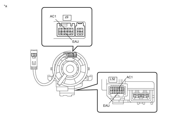
Text in Illustration *a Component without harness connected
(Spiral with Sensor Cable Sub-assembly)
-
NG
REPLACE SPIRAL WITH SENSOR CABLE SUB-ASSEMBLY Click here
OK
-
-
INSPECT STEERING PAD SWITCH RH
-
Remove the steering pad switch RH Click here.
-
Measure the resistance according to the value(s) in the table below.
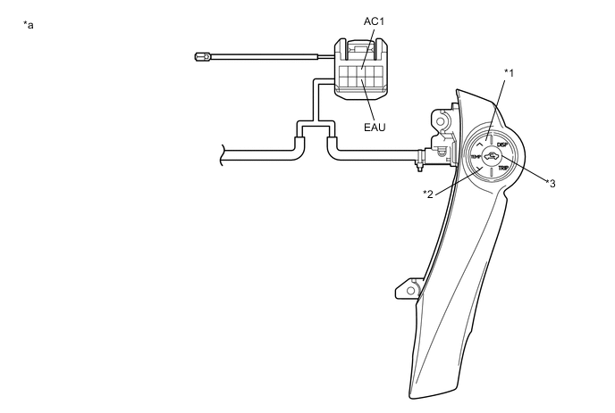
Text in Illustration *1 TEMP + Switch *2 TEMP - Switch *3 R/F Switch - - *a Component without harness connected
(Steering Pad Switch RH)
- - Standard Resistance Tester Connection Condition Specified Condition 3 (AC1) - 8 (EAU) No switch pushed 95 to 105 kΩ 3 (AC1) - 8 (EAU) R/F switch pushed 323 to 335 Ω 3 (AC1) - 8 (EAU) TEMP + switch pushed 980 to 1020 Ω 3 (AC1) - 8 (EAU) TEMP - switch pushed 3048 to 3172 Ω
NG
REPLACE STEERING PAD SWITCH RH Click here
OK
-
-
REPLACE AIR CONDITIONING PANEL (CENTER CLUSTER MODULE CIRCUIT)
-
Replace the air conditioning panel (center cluster module circuit) with a new or known good one Click here.
-
Check that the steering pad switch RH operation returns to normal.
Result Result Proceed to OK A NG (w/ Navigation System (for Navigation Receiver Type)) B NG (w/ Navigation System (for Radio and Display Type)) C NG (w/ Audio and Visual System) D
A
END (AIR CONDITIONING CONTROL ASSEMBLY WAS DEFECTIVE)
B
REPLACE NAVIGATION RECEIVER ASSEMBLY Click here
C
REPLACE RADIO AND DISPLAY RECEIVER ASSEMBLY Click here
D
REPLACE RADIO AND DISPLAY RECEIVER ASSEMBLY Click here
-
-
CHECK HARNESS AND CONNECTOR (CENTER CLUSTER MODULE CIRCUIT - SPIRAL WITH SENSOR CABLE SUB-ASSEMBLY)
-
Measure the resistance according to the value(s) in the table below.
Standard Resistance Tester Connection Condition Specified Condition L52-10 (AC1) - L20-10 (SWO) Always Below 1 Ω L52-10 (AC1) - Body ground Always 10 kΩ or higher
OK
REPLACE AIR CONDITIONING PANEL (CENTER CLUSTER MODULE CIRCUIT) Click here
NG
REPAIR OR REPLACE HARNESS OR CONNECTOR
-