REAR AXLE CARRIER REMOVAL
CAUTION / NOTICE / HINT
Use the same procedure for the RH side and LH side.
The procedure listed below is for the LH side.
PROCEDURE
REMOVE REAR WHEEL
REMOVE UPPER CONSOLE PANEL SUB-ASSEMBLY
LOOSEN NO. 2 WIRE ADJUSTING NUT
REMOVE REAR SUSPENSION ARM COVER
REMOVE REAR FLOOR SIDE MEMBER COVER LH (for LH Side)
REMOVE REAR FLOOR SIDE MEMBER COVER RH (for RH Side)
REMOVE PARKING BRAKE LEVER PROTECTOR
SEPARATE NO. 3 PARKING BRAKE CABLE ASSEMBLY
SEPARATE REAR DISC BRAKE CALIPER ASSEMBLY
REMOVE REAR DISC
REMOVE REAR HEIGHT CONTROL SENSOR SUB-ASSEMBLY (w/ Height Control Sensor)
DISCONNECT SKID CONTROL SENSOR WIRE
REMOVE REAR AXLE HUB AND BEARING ASSEMBLY
REMOVE REAR NO. 1 SUSPENSION ARM ASSEMBLY
REMOVE REAR AXLE CARRIER SUB-ASSEMBLY
-
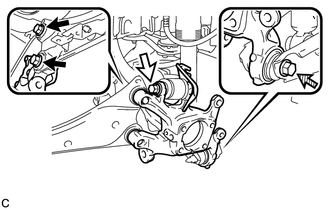

Bolt (A)

Bolt (B)

Bolt (C)
Loosen the 2 bolts (A), bolt (B) and bolt (C).
Note:Because the nuts have their own stoppers, do not turn the nuts. Loosen the bolts with the nuts secured.
Do not remove the bolts.
-
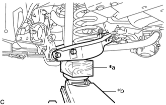
*a
Wooden Block
*b
Jack
Using a jack and wooden block, keep the rear No. 2 suspension arm assembly level.
CAUTION:Do not jack up the rear No. 2 suspension arm assembly too high as the vehicle may fall.
Note:When jacking up the rear No. 2 suspension arm assembly, be sure to jack it up slowly.
Make sure to perform this operation with the vehicle kept as low as possible.
-
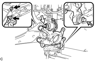
*1
No. 2 Flexible Hose Bracket
Bolt (A)
Bolt (B)
Bolt (C)
Remove the 2 bolts (A), and separate the rear trailing arm assembly from the rear axle carrier sub-assembly.
Remove the bolt (B), nut and No. 2 flexible hose bracket, and then separate the rear upper control arm assembly from the rear axle carrier sub-assembly.
Note:Because the nut has its own stopper, do not turn the nut. Loosen the bolt with the nut secured.
Remove the bolt (C), nut and rear axle carrier sub-assembly from the rear No. 2 suspension arm assembly.
Note:Because the nut has its own stopper, do not turn the nut. Loosen the bolt with the nut secured.
-