DYNAMIC TORQUE CONTROL AWD SYSTEM AWD Control Switch Circuit
DESCRIPTION
The 4WD ECU assembly changes the control mode in response to the "Lock Mode" signal from the AWD lock mode switch (No. 2 combination switch assembly).
WIRING DIAGRAM
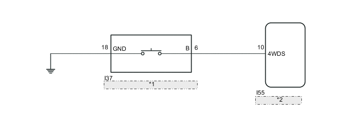
| *1 | AWD Lock Mode Switch (No. 2 Combination Switch Assembly) |
| *2 | 4WD ECU Assembly |
CAUTION / NOTICE / HINT
Note
When the 4WD ECU assembly is replaced with a normal one from another vehicle, it is necessary to perform calibration.
PROCEDURE
-
INSPECT AWD LOCK MODE INDICATOR LIGHT
-
Turn the engine switch off.
-
Connect the GTS to the DLC3.
-
Turn the engine switch on (IG).
-
Turn the GTS on.
-
Enter the following menus: Chassis / Four Wheel Drive / Active Test
-
According to the display on the GTS, perform the Active Test.
Chassis > Four Wheel Drive > Active TestTester Display Measurement Item Control Range Diagnostic Note 4WD LOCK Light AWD lock mode indicator light Indicator light OFF/ON Observe combination meter assembly -
When performing the 4WD LOCK Light Active Test, check 4WD LOCK Light in the Data List.
Chassis > Four Wheel Drive > Data ListTester Display Measurement Item Range Normal Condition Diagnostic Note 4WD LOCK Light AWD lock mode indicator light OFF or ON OFF: AWD lock mode indicator light off
ON: AWD lock mode indicator light on
-
Chassis > Four Wheel Drive > Active TestActive Test Display 4WD LOCK Light Data List Display 4WD LOCK Light Result Proceed to Changes between ON and OFF Does not change between ON and OFF
Does not change between ON and OFF 
REPLACE 4WD ECU ASSEMBLY for LHD: Click here
REPLACE 4WD ECU ASSEMBLY for RHD: Click hereChanges between ON and OFF 
-
-
INSPECT NO. 2 COMBINATION SWITCH ASSEMBLY
-
Turn the engine switch off.
-
Remove the AWD lock mode switch (No. 2 combination switch assembly).
-
Inspect the AWD lock mode switch (No. 2 combination switch assembly).
Result Proceed to OK NG
NG
REPLACE NO. 2 COMBINATION SWITCH ASSEMBLY Click here
OK
-
-
CHECK HARNESS AND CONNECTOR (NO. 2 COMBINATION SWITCH ASSEMBLY - BODY GROUND)
-
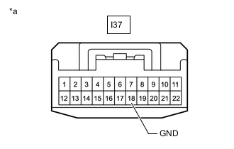
*a Front view of wire harness connector
(to AWD Lock Mode Switch (No. 2 Combination Switch Assembly))
Measure the resistance according to the value(s) in the table below.
Standard Resistance Tester Connection Condition Specified Condition I37-18 (GND) - Body ground Always Below 1 Ω Result Proceed to OK NG
NG
REPAIR OR REPLACE HARNESS OR CONNECTOR
OK
-
-
CHECK HARNESS AND CONNECTOR (NO. 2 COMBINATION SWITCH ASSEMBLY - 4WD ECU ASSEMBLY)
-
Reinstall the AWD lock mode switch (No.2 combination switch assembly).
-
Disconnect the I55 4WD ECU assembly connector.
-
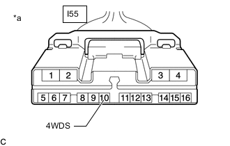
*a Front view of wire harness connector
(to 4WD ECU Assembly)
Measure the resistance according to the value(s) in the table below.
Standard Resistance Tester Connection Switch Condition Specified Condition I55-10 (4WDS) - Body ground Switch pressed and held Below 1 Ω Switch released 10 kΩ or higher Result Proceed to OK NG
OK
REPLACE 4WD ECU ASSEMBLY for LHD: Click here
REPLACE 4WD ECU ASSEMBLY for RHD: Click hereNG
REPAIR OR REPLACE HARNESS OR CONNECTOR
-