LIGHTING SYSTEM ALL Stop Light do not Illuminate
| DTC Code | DTC Name |
|---|---|
| ALL Stop Light do not Illuminate |
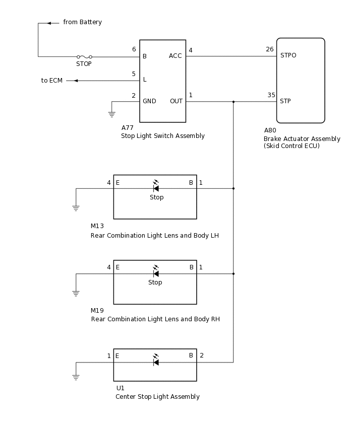
WIRING DIAGRAM
CAUTION / NOTICE / HINT
When replacing the brake actuator assembly (skid control ECU), perform zero point calibration.
When the smart entry start function does not operate, check the entry and start system (start function)*.
*: w/ Entry and Start System
PROCEDURE
CHECK STOP LIGHT OPERATION
Check that the stop lights illuminate when the brakepedal is depressed.
OK
The stop lights illuminate when the brake pedal isdepressed.
Result
Proceed to
OK
NG
OK CHECK CONNECTOR CONNECTION CONDITION
CHECK HARNESS AND CONNECTOR (OUT)
Disconnect the A80 brake acyuator assembly.
Disconnect the A77 stoplight light switch assembly connector.
Disconnect the M13 rear combination light lens and body LH connector.
Disconnect the M19 rear combination light lens and body RH connector.
Disconnect the U1 center stop light assembly connector.
Measure the resistance according to the value(s) in the table below.
Standard Resistance
Tester Connection
Condition
Specified Condition
A80-35 (STP) - A77-1 (OUT)
Always
Below 1 Ω
A80-35 (STP) - Body ground
Always
10 kΩ or higher
Result
Proceed to
OK
NG
NG REPAIR OR REPLACE HARNESS OR CONNECTOR
CHECK STOP LIGHT SWITCH ASSEMBLY (OUT)
Disconnect the M13 rear combination light lens and body LH connector.
Disconnect the M19 rear combination light lens and body RH connector.
Disconnect the U1 center stop light assembly connector.
Measure the voltage according to the value(s) in the table below.
Standard Resistance
Tester Connection
Condition
Specified Condition
A77-1 (OUT) - Body ground
Brake pedal depressed
11 to 14 V
Result
Proceed to
OK
NG
OK REPAIR OR REPLACE REAR COMINATION LIGHT LENS AND BODY AND CENTER STOP LIGHT ASSEMBLY
Inspect the rear combination light lens and body.
Inspect the center stop light assembly.