SFI SYSTEM(w/ Canister Pump Module), Diagnostic DTC:P16B871
| DTC Code | DTC Name |
|---|---|
| P16B871 | Multi Flow Control Valve Actuator Stuck |
DESCRIPTION
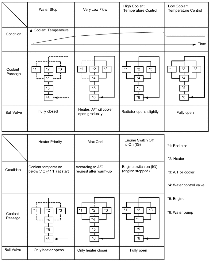
In the water control valve, the ball valve installed at the opening is rotated by the DC motor. This changes the coolant flow distributed to each port of the radiator, heater and devices (A/T oil cooler, etc.) or stops the coolant flow partially or completely, in order to improve fuel economy and air conditioning performance.
This is a highly functional coolant control valve that is used instead of a conventional thermostat.
-
Coolant flow control: Variable control from water stop to maximum flow is performed for fast warm-up and knocking prevention
-
Coolant passage control:
-
Fully closed for fast engine warm-up
-
Radiator port closes slightly in low and medium load ranges (high coolant temperature control)
-
Radiator port opens slightly in the knocking range at high loads (low coolant temperature control)
-
Heater port opens when heater is requested
-
Heater port closes when air conditioning max cool is requested
| DTC No. | Detection Item | DTC Detection Condition | Trouble Area | MIL | Memory | Note |
|---|---|---|---|---|---|---|
| P16B871 | Multi Flow Control Valve Actuator Stuck | Operation speed of ball valve of water control valve is below 5°/65 ms (2 trip detection logic). | Water control valve | Comes on | DTC stored | SAE: P16B8 |
MONITOR DESCRIPTION
When the actual angle change amount of the ball valve of the water control valve is low even though the ball valve of the water control valve is operating, the valve is judged to be stuck and the ECM stores a DTC.
MONITOR STRATEGY
| Required Sensors/Components | Water control valve |
| Frequency of Operation | Continuous |
CONFIRMATION DRIVING PATTERN
-
Connect the GTS to the DLC3.
-
Turn the engine switch on (IG).
-
Turn the GTS on.
-
Clear the DTCs (even if no DTCs are stored, perform the clear DTC procedure).
-
Turn the engine switch off and wait for at least 30 seconds.
-
Start the engine.
-
Idle the engine for 120 seconds or more.
-
Turn the engine switch off and wait for at least 30 seconds.
-
Turn the engine switch on (IG).
-
Turn the GTS on.
-
Enter the following menus: Powertrain / Engine / Trouble Codes.
-
Read the pending DTCs.
Tech Tips
-
If a pending DTC is output, the system is malfunctioning.
-
If a pending DTC is not output, perform the following procedure.
-
-
Enter the following menus: Powertrain / Engine / Utility / All Readiness.
-
Input the DTC: P16B871.
-
Check the DTC judgment result.
GTS Display Description NORMAL
-
DTC judgment completed
-
System normal
ABNORMAL
-
DTC judgment completed
-
System abnormal
INCOMPLETE
-
DTC judgment not completed
-
Perform driving pattern after confirming DTC enabling conditions
Tech Tips
-
If the judgment result shows NORMAL, the system is normal.
-
If the judgment result shows ABNORMAL, the system has a malfunction.
-
CAUTION / NOTICE / HINT
Tech Tips
Read Freeze Frame Data using the GTS. The ECM records vehicle and driving condition information as Freeze Frame Data the moment a DTC is stored. When troubleshooting, Freeze Frame Data can help determine if the vehicle was moving or stationary, if the engine was warmed up or not, if the air fuel ratio was lean or rich, and other data from the time the malfunction occurred.
PROCEDURE
-
CHECK ANY OTHER DTCS OUTPUT (IN ADDITION TO DTC P16B871)
-
Connect the GTS to the DLC3.
-
Turn the engine switch on (IG).
-
Turn the GTS on.
-
Enter the following menus: Powertrain / Engine / Trouble Codes.
-
Read the DTCs.
Powertrain > Engine > Trouble CodesResult Result Proceed to DTC P16B871 is output A DTC P16B871 and other DTCs are output B Tech Tips
If any DTCs other than P16B871 are output, troubleshoot those DTCs first.
B 
GO TO DTC CHART Click here
A 
-
-
CUSTOMER PROBLEM ANALYSIS AND CHECK VEHICLE (CHECK FOR OVERHEATING)
-
Perform a customer problem analysis to check whether overheating occurred.
Tech Tips
Check whether "High coolant temperature warning light" was displayed on the combination meter.
Result Result Proceed to Overheating occurred A Overheating did not occur B
B 
GO TO STEP 7 Click here
A
-
-
CHECK VEHICLE (CHECK FOR OVERHEATING)
-
Check the engine coolant quantity.
Result Result Proceed to At or below reserve tank LOW level or trace of coolant boiling over A At or above reservoir tank LOW level and no trace of coolant boiling over B
B
GO TO STEP 7 Click here
A
-
-
CHECK FOR COOLANT LEAK
-
Check the engine cooling system for coolant leaks.
OK No leaks. Result Proceed to OK NG
OK
GO TO STEP 6 Click here
NG
-
-
REPAIR OR REPLACE MALFUNCTIONING PARTS, COMPONENT AND AREA
-
Repair any engine coolant leaks.
Tech Tips
Check for damage to parts due to overheating and replace any abnormal parts.
Result Proceed to NEXT
NEXT
-
-
ADD COOLANT
-
Fill the reservoir tank up to the FULL line with engine coolant.
Tech Tips
Add engine coolant and perform air bleeding after repair.
Result Proceed to NEXT
NEXT
-
-
CLEAR DTC
-
Connect the GTS to the DLC3.
-
Turn the engine switch on (IG).
-
Turn the GTS on.
-
Clear the DTCs.
Powertrain > Engine > Clear DTCs -
Turn the engine switch off and wait for at least 30 seconds.
Result Proceed to NEXT
NEXT
-
-
PERFORM ACTIVE TEST USING GTS (CONTROL THE MULTI FLOW CONTROL VALVE POSITION)
-
Connect the GTS to the DLC3.
-
Turn the engine switch on (IG).
-
Turn the GTS on.
-
Enter the following menus: Powertrain / Engine / Active Test / Control the Multi Flow Control Valve Position / Data List / Actual Multi Flow Control Valve Position.
Powertrain > Engine > Active TestActive Test Display Control the Multi Flow Control Valve Position Data List Display Actual Multi Flow Control Valve Position -
Read the Data List when the water control valve is operated.
OK The value of the Data List item "Actual Multi Flow Control Valve Position" follows the command value and changes smoothly when the Active Test is operated in all ranges. Result Proceed to OK NG
NG
INSPECT ECM (INTERNAL CIRCUIT) Click here
OK
-
-
CLEAR DTC
-
Connect the GTS to the DLC3.
-
Turn the engine switch on (IG).
-
Turn the GTS on.
-
Clear the DTCs.
Powertrain > Engine > Clear DTCs -
Turn the engine switch off and wait for at least 30 seconds.
Result Proceed to NEXT
NEXT
-
-
CHECK WHETHER DTC OUTPUT RECURS (DTC P16B871)
-
Start the engine.
-
Idle the engine for 120 seconds or more.
-
Turn the engine switch off and wait for at least 30 seconds.
-
Start the engine from a cold condition.
-
Drive the vehicle on urban roads until the Data List item "Coolant Temperature Controlling Value" rises to 60°C (140°F) or higher.
-
Turn the air conditioning on (max cool).
-
Turn the GTS on.
-
Enter the following menus: Powertrain / Engine / Utility / All Readiness.
Powertrain > Engine > UtilityTester Display All Readiness -
Input the DTC: P16B871.
-
Check the DTC judgment result.
Result Result Proceed to NORMAL
(DTCs are not output)
A ABNORMAL
(DTC P16B871 is output)
B
A
REPLACE ENGINE COOLANT Click here Even when no DTC is output, replace the coolant because foreign matter trapped in the coolant may cause temporary locking.
B
GO TO STEP 12 Click here
-
-
INSPECT ECM (INTERNAL CIRCUIT)
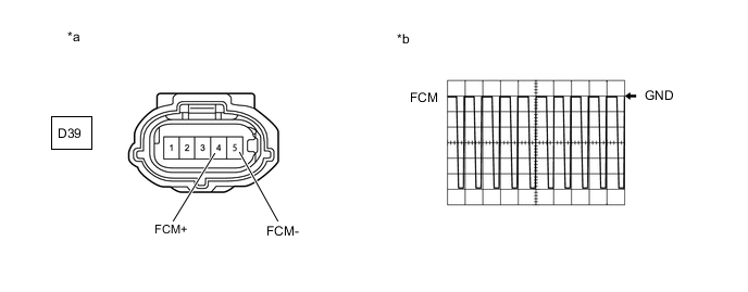
*a Front view of wire harness connector
(to Water Control Valve)
*b Waveform of FCM+ terminal and FCM- terminal during fail-safe
-
Disconnect the water control valve connector.
-
Inspect the ECM using an oscilloscope.
-
Turn the engine switch on (IG).
-
While the engine switch on (IG), check the waveform the terminals of the water control valve connector.
ECM Terminal Name D39-4 (FCM+) - D39-5 (FCM-) Tester Range 2 V/DIV., 1 ms./DIV. Condition Engine switch on (IG) -
While the engine switch is on (IG), check the waveform between the FCM+ terminal and FCM- terminal during fail-safe.
Standard 25% duty waveform is output Tech Tips
-
Check the operation circuit of the ECM by checking the waveform during fail-safe.
-
Because fail-safe is prohibited when the ambient temperature is 0°C (32°F) or less, work in a location where the ambient temperature is 5°C (41°F) or higher.
-
DTCs may be stored during this inspection. Check for DTCs and clear them using the GTS.
Result Proceed to OK NG -
NG
CHECK HARNESS AND CONNECTOR (WATER CONTROL VALVE - ECM) Click here
OK
-
-
REPLACE WATER CONTROL VALVE
-
Replace the water control valve.
Result Proceed to NEXT
NEXT
REPLACE ENGINE COOLANT Click here
-
-
CHECK HARNESS AND CONNECTOR (WATER CONTROL VALVE - ECM)
-
Disconnect the water control valve connector.
-
Disconnect the ECM connector.
-
Measure the resistance according to the value(s) in the table below.
Standard Resistance Tester Connection Condition Specified Condition D39-4 (FCM+) - D2-15 (FCM+) Always Below 1 Ω D39-5 (FCM-) - D2-16 (FCM-) Always Below 1 Ω D39-4 (FCM+) or D2-15 (FCM+) - Body ground and other terminals Always 10 kΩ or higher D39-5 (FCM-) or D2-16 (FCM-) - Body ground and other terminals Always 10 kΩ or higher Result Proceed to OK NG
OK
REPLACE ECM Click here
NG
REPAIR OR REPLACE HARNESS OR CONNECTOR
-