MONOLITHIC CONVERTER INSTALLATION
PROCEDURE
-
INSTALL MANIFOLD STAY
-
Install the manifold stay with the 2 bolts.
- Torque:
- 43 N*m { 438 kgf*cm, 32 ft.*lbf }
-
-
INSTALL CONVERTER ASSEMBLY RH
-
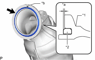
*1 Exhaust Manifold Converter Sub-assembly *2 Gasket *a 1.5 mm (0.0591 in.) or less *b Knock Pin Install a new gasket to the converter assembly RH as shown in the illustration.
Note
When reusing the converter assembly RH, thoroughly clean the gasket groove so that no old gasket remains.
Tech Tips
Fully insert the gasket into the gasket groove of the converter assembly RH.
-
Set a new exhaust pipe clamp RH to the converter assembly RH.
Note
Make sure the end of the exhaust pipe clamp RH does not open 140 mm or more (standard amount approximately 60 mm).
-
Temporarily install the manifold stay to the converter assembly RH with the nut.
Note
Tighten the nut by hand until it contacts the surface.
-
Align the converter assembly RH with the knock hole on the No. 1 turbocharger sub-assembly side to connect the converter assembly RH.
Note
Make sure that there is a knock pin on the converter assembly RH.
-
Tighten the nut.
- Torque:
- 43 N*m { 438 kgf*cm, 32 ft.*lbf }
-
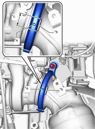
*a Alignment Protrusion on Exhaust Pipe Clamp Side RH *b Alignment Protrusion on Converter Assembly RH Side *c Position Alignment Range Align the flange surfaces of the No. 1 turbocharger sub-assembly and converter assembly RH, and then temporarily install the exhaust pipe clamp RH.
Tech Tips
Align the position alignment protrusions on the exhaust pipe clamp RH side to within the range of the position alignment protrusions on the converter assembly RH side.
-
Tighten the exhaust pipe clamp RH.
- Torque:
- 25 N*m { 255 kgf*cm, 18 ft.*lbf }
-
-
INSTALL NO. 2 MANIFOLD STAY
-
Install the No. 2 manifold stay with the 2 bolts.
- Torque:
- 43 N*m { 438 kgf*cm, 32 ft.*lbf }
-
-
INSTALL CONVERTER ASSEMBLY LH
-
*1 Converter Assembly LH *2 Gasket *a 1.5 mm (0.0591 in.) or less *b Knock Pin Install a new gasket to the converter assembly LH as shown in the illustration.
Note
When reusing the converter assembly LH, thoroughly clean the gasket groove so that no old gasket remains.
Tech Tips
Fully insert the gasket into the gasket groove of the converter assembly LH.
-
Set a new exhaust pipe clamp LH to the converter assembly LH.
Note
Make sure the end of the exhaust pipe clamp LH does not open 140 mm or more (standard amount approximately 60 mm).
-
Temporarily install the manifold stay to the converter assembly LH with the nut.
Note
Tighten the nut by hand until it contacts the surface.
-
Align the converter assembly LH with the knock hole on the No. 2 turbocharger sub-assembly side to connect the converter assembly RH.
Note
Make sure that there is a knock pin on the converter assembly LH.
-
Tighten the nut.
- Torque:
- 43 N*m { 438 kgf*cm, 32 ft.*lbf }
-
*a Alignment Protrusion on Exhaust Pipe Clamp LH Side *b Alignment Protrusion on Converter Assembly LH Side *c Position Alignment Range Align the flange surfaces of the No. 2 turbocharger sub-assembly and converter assembly LH, and then temporarily install the exhaust pipe clamp LH.
Tech Tips
Align the position alignment protrusions on the exhaust pipe clamp LH side to within the range of the position alignment protrusions on the converter assembly LH side.
-
Tighten the exhaust pipe clamp LH.
- Torque:
- 25 N*m { 255 kgf*cm, 18 ft.*lbf }
-
-
INSTALL NO. 1 VACUUM PIPE (w/ GPF)
-
Using a 14 mm union nut wrench, connect the No. 1 vacuum pipe to the converter assembly RH.
- Torque:
- Specified tightening torque
- 30 N*m { 306 kgf*cm, 22 ft.*lbf }
Tech Tips
-
Calculate the torque wrench reading when changing the fulcrum length of the torque wrench.
-
When using a union nut wrench (fulcrum length of 25 mm (0.984 in.)) + torque wrench (fulcrum length of 180 mm (7.09 in.)): 26.3 N*m (268 kgf*cm, 19 ft.*lbf)
-
Install the No. 1 vacuum pipe with the bolt.
- Torque:
- 21 N*m { 214 kgf*cm, 15 ft.*lbf }
-
Install the vacuum transmitting hose assembly to the differential pressure sensor and No. 1 vacuum pipe, and slide the 2 clips to secure the hoses.
-
-
INSTALL NO. 2 VACUUM PIPE (w/ GPF)
-
Using a 14 mm union nut wrench, connect the No. 2 vacuum pipe to the converter assembly LH.
- Torque:
- Specified tightening torque
- 30 N*m { 306 kgf*cm, 22 ft.*lbf }
Tech Tips
-
Calculate the torque wrench reading when changing the fulcrum length of the torque wrench.
-
When using a union nut wrench (fulcrum length of 25 mm (0.984 in.)) + torque wrench (fulcrum length of 180 mm (7.09 in.)): 26.3 N*m (268 kgf*cm, 19 ft.*lbf)
-
Install the No. 2 vacuum pipe with the bolt.
- Torque:
- 21 N*m { 214 kgf*cm, 15 ft.*lbf }
-
Install the No. 2 vacuum transmitting hose assembly to the differential pressure sensor and No. 2 vacuum pipe, and slide the 2 clips to secure the hoses.
-
-
INSTALL NO. 2 TURBO INSULATOR
-
Install the No. 2 turbo insulator with the 3 bolts.
- Torque:
- 21 N*m { 214 kgf*cm, 15 ft.*lbf }
-
-
INSTALL NO. 4 TURBO INSULATOR
-
Install the No. 4 turbo insulator with the 3 bolts.
- Torque:
- 21 N*m { 214 kgf*cm, 15 ft.*lbf }
-
-
INSTALL AIR FUEL RATIO SENSOR
-
INSTALL ENGINE ASSEMBLY WITH TRANSMISSION (for 2WD)
-
INSTALL ENGINE ASSEMBLY WITH TRANSMISSION (for AWD)
-
INSPECT FOR EXHAUST GAS LEAK