METER / GAUGE SYSTEM Engine Coolant Temperature Receiver Gauge Malfunction
| DTC Code | DTC Name |
|---|---|
| Engine Coolant Temperature Receiver Gauge Malfunction |
DESCRIPTION
In this circuit, the combination meter assembly receives engine coolant temperature signals from the ECM using the CAN communication system. The combination meter assembly displays the engine coolant temperature that is calculated based on the data received from the ECM.
WIRING DIAGRAM
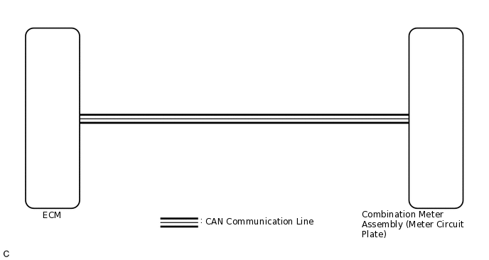
CAUTION / NOTICE / HINT
If there is an open or short in the engine coolant temperature sensor circuit, the ECM stores DTCs. Troubleshoot the SFI system or ECD system.
SFI system for 1NR-FE:Click here
SFI system for 1ZR-FAE:Click here
ECD system for 1ND-TV:Click here
ECD system for 1AD-FTV:Click here
PROCEDURE
CHECK CAN COMMUNICATION SYSTEM
Check if CAN communication DTCs are output.
Result
Result
Proceed to
CAN communication DTCs are not output.
A
CAN communication DTCs are output.
B
PERFORM ACTIVE TEST USING GTS (WATER TEMPERATURE METER OPERATION)
Connect the GTS to the DLC3.
Turn the ignition switch to ON.
Turn the GTS on.
Enter the following menus: Body Electrical / Combination Meter / Active Test.
Check the operation by referring to the table below.
for Multi-information display (Dot LCD type)
Body Electrical > Combination Meter > Active Test
Tester Display
Measurement Item
Control Range
Diagnostic Note
Water Temperature Meter Operation
Engine coolant temperature receiver gauge
OFF, Low, Normal, High
-
Body Electrical > Combination Meter > Active Test
Tester Display
Water Temperature Meter Operation
for Multi-information display (Segment LCD type)
Body Electrical > Combination Meter > Active Test
Tester Display
Measurement Item
Control Range
Diagnostic Note
Water Temperature Meter Operation
Engine coolant temperature receiver gauge
OFF, LOW, NORMAL, HIGH
-
Body Electrical > Combination Meter > Active Test
Tester Display
Water Temperature Meter Operation
OK
Engine coolant temperature receiver gauge indication is normal.
Result
Proceed to
OK
NG
READ VALUE USING GTS (COOLANT TEMPERATURE)
Connect the GTS to the DLC3.
Turn the ignition switch to ON.
Turn the GTS on.
Enter the following menus: Body Electrical / Combination Meter / Data List.
Check the values by referring to the table below.
Body Electrical > Combination Meter > Data List
Tester Display
Measurement Item
Range
Normal Condition
Diagnostic Note
Coolant Temperature
Engine coolant temperature
0 to 127.5°C (0 to 261.5°F)
1NR-FE, 1ZR-FAE:
75 to 100 °C (167 to 212°F) (After warming up engine)
1AD-FTV:
60 to 90 °C (140 to 194°F) (After warming up engine)
1ND-TV:
75 to 90°C (167 to 194°F) (After warming up engine)
-
Body Electrical > Combination Meter > Data List
Tester Display
Coolant Temperature
OK
Engine coolant temperature displayed on the GTS is almost the same as the engine coolant temperature receiver gauge indication.
Tip:When the Data List values and engine coolant temperature receiver gauge values match, a signal output error of the ECM or an internal malfunction of the combination meter assembly is suspected.
When the Data List values and engine coolant temperature receiver gauge values do not match, an internal malfunction of the combination meter assembly is suspected.
Result
Proceed to
OK
NG
CHECK FOR DTC
Check if SFI system, ECD system or meter / gauge system DTCs are output.
SFI system for 1NR-FE:Click here
SFI system for 1ZR-FAE:Click here
ECD system for 1ND-TV:Click here
ECD system for 1AD-FTV:Click here
Meter / gauge system:Click here
Result
Result
Proceed to
DTCs are not output.
A
DTCs are output (for SFI system).
B
DTCs are output (for ECD system).
C
DTC B1503 is output.
D
READ VALUE USING GTS (COOLANT TEMP, COOLANT TEMPERATURE)
Connect the GTS to the DLC3.
Turn the ignition switch to ON.
Turn the GTS on.
Enter the following menus:
for Engine and ECT: Powertrain / Engine and ECT / Data List.
for Combination Meter: Body Electrical / Combination Meter / Data List.
Check the values by referring to the table below.
Engine and ECT (for Gasoline)
Powertrain > Engine and ECT > Data List
Tester Display
Measurement Item
Range
Normal Condition
Reference Value
Diagnostic Note
Coolant Temp
Coolant temperature
Min.: -40°C (-40°F), Max.: 140°C (284°F)
75 to 100°C (167 to 212°F): After warming up
-
Stored as Freeze Frame Data: Yes
This is the engine coolant temperature.
Tip:After warming up the engine, the engine coolant temperature is 75 to 100°C (167 to 212°F).
After a long soak, the engine coolant temperature, intake air temperature and ambient temperature are approximately equal.
If the value is -40°C (-40°F), or 140°C (284°F), the sensor circuit is open or shorted.
Check if the engine overheats when the value indicates 140°C (284°F).
Powertrain > Engine and ECT > Data List
Tester Display
Coolant Temp
Engine and ECT (for Diesel)
Powertrain > Engine and ECT > Data List
Tester Display
Measurement Item
Type
Range
Normal Condition
Reference Value
Diagnostic Note
Coolant Temp
Engine coolant temperature
Sensor output (engine coolant temperature sensor)
Min.: -40°C, Max.: 140°C
1AD-FTV:
After warming up engine: 60 to 90°C (140 to 194°F)
1ND-TV:
After warming up engine: 75 to 90°C (167 to 194°F)
1AD-FTV:
-
1ND-TV:
After warming up engine: 75°C (167°F)
1AD-FTV: If the value is -40°C (-40°F) or 140°C (284°F), the sensor circuit is open or shorted.
1ND-TV: If the value is 30°C (-22°F) or less or 120°C (248°F) or more, the sensor circuit is open or shorted.
After a long soak, the coolant temperature, intake air temperature and ambient temperature are approximately equal.
Cause of out of range:
Engine coolant temperature sensor
Thermostat
Symptoms when out of range:
Difficult to start when engine is cold, rough idle, black smoke, lack of power
Powertrain > Engine and ECT > Data List
Tester Display
Coolant Temp
Combination Meter
Body Electrical > Combination Meter > Data List
Tester Display
Measurement Item
Range
Normal Condition
Diagnostic Note
Coolant Temperature
Engine coolant temperature
0 to 127.5°C (0 to 261.5°F)
1NR-FE, 1ZR-FAE:
75 to 100 °C (167 to 212°F) (After warming up engine)
1AD-FTV:
60 to 90 °C (140 to 194°F) (After warming up engine)
1ND-TV:
75 to 90°C (167 to 194°F) (After warming up engine)
-
Body Electrical > Combination Meter > Data List
Tester Display
Coolant Temperature
Result
Result
Proceed to
Data List values of the ECUs match.
A
Data List values of the ECUs do not match.
B
Tip:When the Data List values of the ECUs match, an internal malfunction of the ECM is suspected.
When the Data List values of the ECUs do not match, a signal output error of the ECM or an internal malfunction of the combination meter assembly is suspected.
B REPLACE ECM
REPLACE COMBINATION METER ASSEMBLY
Replace the combination meter assembly with a new or known good one.
OK
The operation of the engine coolant temperature receiver gauge returns to normal.
Result
Proceed to
OK
NG
OK END
NG REPLACE ECM