TOYOTA PARKING ASSIST-SENSOR SYSTEM(except Hatchback), Diagnostic DTC:C1AEC
| DTC Code | DTC Name |
|---|---|
| C1AEC | Front Sensor Communication Malfunction |
DESCRIPTION
This DTC is stored when there is a short circuit in the communication line between the front sensors and the ECU, or when there is a malfunction in a front sensor.
DTC No. |
Detection Item |
DTC Detection Condition |
Trouble Area |
|---|---|---|---|
C1AEC |
Front Sensor Communication Malfunction |
A short circuit in the communication line between the front sensors and ECU or a malfunction in a front sensor during initialization mode after the ignition switch is turned to ON. |
|
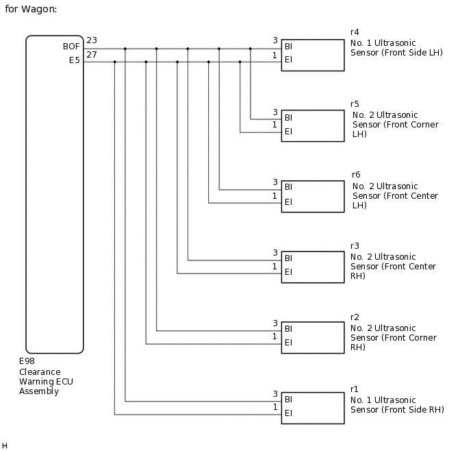
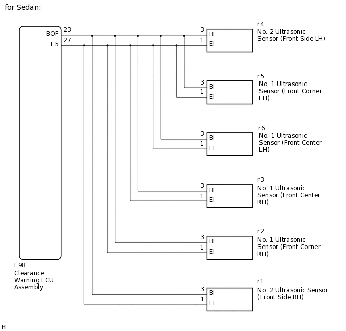
WIRING DIAGRAM
CAUTION / NOTICE / HINT
If DTCs are output after repairs, turn the ignition switch to ON and turn the back sonar or clearance sonar switch assembly on. Then clear the DTCs.
Depending on the parts that are replaced during vehicle inspection or maintenance, performing initialization may be needed. Refer to Initialization.
PROCEDURE
CONFIRM MODEL
Choose the model to be inspected.
Result
Result
Proceed to
for Wagon
A
for Sedan
B
B CHECK HARNESS AND CONNECTOR (CLEARANCE WARNING ECU ASSEMBLY - ULTRASONIC SENSOR (FRONT SONARS))Click here
CHECK HARNESS AND CONNECTOR (CLEARANCE WARNING ECU ASSEMBLY - ULTRASONIC SENSOR (FRONT SONARS))
Disconnect the E98 clearance warning ECU assembly connector.
Disconnect the r4 No. 1 ultrasonic sensor (front side LH) connector.
Disconnect the r5 No. 2 ultrasonic sensor (front corner LH) connector.
Disconnect the r6 No. 2 ultrasonic sensor (front center LH) connector.
Disconnect the r3 No. 2 ultrasonic sensor (front center RH) connector.
Disconnect the r2 No. 2 ultrasonic sensor (front corner RH) connector.
Disconnect the r1 No. 1 ultrasonic sensor (front side RH) connector.
Measure the resistance according to the value(s) in the table below.
Standard Resistance
Tester Connection
Condition
Specified Condition
E98-23 (BOF) - Body ground
Always
10 kΩ or higher
E98-23 (BOF) - E98-27 (E5)
Always
10 kΩ or higher
Result
Proceed to
OK
NG
NG REPAIR OR REPLACE HARNESS OR CONNECTOR
INSPECT NO. 1 ULTRASONIC SENSOR (FRONT SIDE LH)
Remove the No. 1 ultrasonic sensor (front side LH).
-
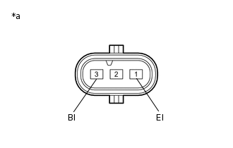
*a
Component without harness connected
(No. 1 Ultrasonic Sensor (Front Side LH))
Measure the resistance according to the value(s) in the table below.
Standard Resistance
Tester Connection
Condition
Specified Condition
3 (BI) - 1 (EI)
Always
10 kΩ or higher
Result
Proceed to
OK
NG
INSPECT NO. 2 ULTRASONIC SENSOR (FRONT CORNER LH)
Remove the No. 2 ultrasonic sensor (front corner LH).
-
*a
Component without harness connected
(No. 2 Ultrasonic Sensor (Front Corner LH))
Measure the resistance according to the value(s) in the table below.
Standard Resistance
Tester Connection
Condition
Specified Condition
3 (BI) - 1 (EI)
Always
10 kΩ or higher
Result
Proceed to
OK
NG
INSPECT NO. 2 ULTRASONIC SENSOR (FRONT CENTER LH)
Remove the No. 2 ultrasonic sensor (front center LH).
-
*a
Component without harness connected
(No. 2 Ultrasonic Sensor (Front Center LH))
Measure the resistance according to the value(s) in the table below.
Standard Resistance
Tester Connection
Condition
Specified Condition
3 (BI) - 1 (EI)
Always
10 kΩ or higher
Result
Proceed to
OK
NG
INSPECT NO. 2 ULTRASONIC SENSOR (FRONT CENTER RH)
Remove the No. 2 ultrasonic sensor (front center RH).
-
*a
Component without harness connected
(No. 2 Ultrasonic Sensor (Front Center RH))
Measure the resistance according to the value(s) in the table below.
Standard Resistance
Tester Connection
Condition
Specified Condition
3 (BI) - 1 (EI)
Always
10 kΩ or higher
Result
Proceed to
OK
NG
INSPECT NO.2 ULTRASONIC SENSOR (FRONT CORNER RH)
Remove the No. 2 ultrasonic sensor (front corner RH).
-
*a
Component without harness connected
(No. 2 Ultrasonic Sensor (Front Corner RH))
Measure the resistance according to the value(s) in the table below.
Standard Resistance
Tester Connection
Condition
Specified Condition
3 (BI) - 1 (EI)
Always
10 kΩ or higher
Result
Proceed to
OK
NG
INSPECT NO. 1 ULTRASONIC SENSOR (FRONT SIDE RH)
Remove the No. 1 ultrasonic sensor (front side RH).
-
*a
Component without harness connected
(No. 1 Ultrasonic Sensor (Front Side RH))
Measure the resistance according to the value(s) in the table below.
Standard Resistance
Tester Connection
Condition
Specified Condition
3 (BI) - 1 (EI)
Always
10 kΩ or higher
Result
Result
Proceed to
OK
A
NG
B
CHECK HARNESS AND CONNECTOR (CLEARANCE WARNING ECU ASSEMBLY - ULTRASONIC SENSOR (FRONT SONARS))
Disconnect the E98 clearance warning ECU assembly connector.
Disconnect the r4 No. 2 ultrasonic sensor (front side LH) connector.
Disconnect the r5 No. 1 ultrasonic sensor (front corner LH) connector.
Disconnect the r6 No. 1 ultrasonic sensor (front center LH) connector.
Disconnect the r3 No. 1 ultrasonic sensor (front center RH) connector.
Disconnect the r2 No. 1 ultrasonic sensor (front corner RH) connector.
Disconnect the r1 No. 2 ultrasonic sensor (front side RH) connector.
Measure the resistance according to the value(s) in the table below.
Standard Resistance
Tester Connection
Condition
Specified Condition
E98-23 (BOF) - Body ground
Always
10 kΩ or higher
E98-23 (BOF) - E98-27 (E5)
Always
10 kΩ or higher
Result
Proceed to
OK
NG
NG REPAIR OR REPLACE HARNESS OR CONNECTOR
INSPECT NO. 2 ULTRASONIC SENSOR (FRONT SIDE LH)
Remove the No. 2 ultrasonic sensor (front side LH).
-
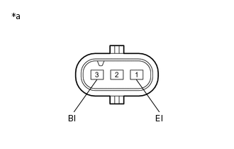
*a
Component without harness connected
(No. 2 Ultrasonic Sensor (Front Side LH))
Measure the resistance according to the value(s) in the table below.
Standard Resistance
Tester Connection
Condition
Specified Condition
3 (BI) - 1 (EI)
Always
10 kΩ or higher
Result
Proceed to
OK
NG
INSPECT NO. 1 ULTRASONIC SENSOR (FRONT CORNER LH)
Remove the No. 1 ultrasonic sensor (front corner LH).
-
*a
Component without harness connected
(No. 1 Ultrasonic Sensor (Front Corner LH))
Measure the resistance according to the value(s) in the table below.
Standard Resistance
Tester Connection
Condition
Specified Condition
3 (BI) - 1 (EI)
Always
10 kΩ or higher
Result
Proceed to
OK
NG
INSPECT NO. 1 ULTRASONIC SENSOR (FRONT CENTER LH)
Remove the No. 1 ultrasonic sensor (front center LH).
-
*a
Component without harness connected
(No. 1 Ultrasonic Sensor (Front Center LH))
Measure the resistance according to the value(s) in the table below.
Standard Resistance
Tester Connection
Condition
Specified Condition
3 (BI) - 1 (EI)
Always
10 kΩ or higher
Result
Proceed to
OK
NG
INSPECT NO. 1 ULTRASONIC SENSOR (FRONT CENTER RH)
Remove the No. 1 ultrasonic sensor (front center RH).
-
*a
Component without harness connected
(No. 1 Ultrasonic Sensor (Front Center RH))
Measure the resistance according to the value(s) in the table below.
Standard Resistance
Tester Connection
Condition
Specified Condition
3 (BI) - 1 (EI)
Always
10 kΩ or higher
Result
Proceed to
OK
NG
INSPECT NO. 1 ULTRASONIC SENSOR (FRONT CORNER RH)
Remove the No. 1 ultrasonic sensor (front corner RH).
-
*a
Component without harness connected
(No. 1 Ultrasonic Sensor (Front Corner RH))
Measure the resistance according to the value(s) in the table below.
Standard Resistance
Tester Connection
Condition
Specified Condition
3 (BI) - 1 (EI)
Always
10 kΩ or higher
Result
Proceed to
OK
NG
INSPECT NO. 2 ULTRASONIC SENSOR (FRONT SIDE RH)
Remove the No. 2 ultrasonic sensor (front side RH).
-
*a
Component without harness connected
(No. 2 Ultrasonic Sensor (Front Side RH))
Measure the resistance according to the value(s) in the table below.
Standard Resistance
Tester Connection
Condition
Specified Condition
3 (BI) - 1 (EI)
Always
10 kΩ or higher
Result
Result
Proceed to
OK
A
NG
B