STOP AND START SYSTEM TERMINALS OF ECU
ENGINE STOP AND START ECU
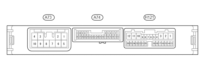
Disconnect the A73, A74 and H121 engine stop and start ECU connector.
Measure the resistance and voltage according to the value(s) in the table below.
Terminal No.
(Symbol)
Wiring Color
Terminal Description
Condition
Specified Condition
A73-5 (+B) - Body ground
G - Body ground
Power source of engine stop and start ECU
Ignition switch ON
9.5 to 14 V
A73-7 (BIN) - Body ground
L - Body ground
Battery
Always
9.5 to 14 V
A73-8 (GND) - Body ground
W-B - Body ground
Ground
Always
Below 1 Ω
A74-10 (NE) - Body ground
P - Body ground
Engine speed signal from ECM
Always
10 kΩ or higher
A74-17 (VB-) - Body ground
W-B - Body ground
Ground
Always
Below 1 Ω
H121-15 (CANH) - Body ground
P - Body ground
CAN communication
Always
200 Ω or higher
H121-16 (CANL) - Body ground
W - Body ground
CAN communication
Always
200 Ω or higher
H121-17 (IG1) - Body ground
L - Body ground
Ignition switch signal
Ignition switch ON
9.5 to 14 V
H121-19 (ACC) - Body ground
GR - Body ground
Ignition switch signal
Ignition switch ACC
9.5 to 14 V
H121-20 (IG2) - Body ground
P - Body ground
Ignition switch signal
Ignition switch ON
9.5 to 14 V
Reconnect the A73, A74 and H121 engine stop and start ECU connector.
Measure the resistance and voltage according to the value(s) in the table below.
Terminal No.
(Symbol)
Wiring Color
Terminal Description
Condition
Specified Condition
A74-3 (BRE2) - Body ground
G - Body ground
Ground (vacuum sensor assembly (brake booster pressure sensor))
Always
Below 1 Ω
A74-7 (BNT1) - A73-8 (GND)
R - W-B
Engine hood courtesy switch (hood lock assembly) signal
Ignition switch ON
Engine stopped
Engine hood closed
0 to 1.5 V
Ignition switch ON
Engine stopped
Engine hood open
8 to 14 V
A74-10 (NE) - A73-8 (GND)
P - W-B
Engine speed signal from ECM
Idling after engine warmed up
Pulse generation (see waveform 1)
A74-11 (CLU) - A73-8 (GND)
W - W-B
Clutch switch assembly (for upper) signal
Ignition switch ON
Clutch pedal released
8 to 14 V
Ignition switch ON
Clutch pedal fully depressed
Below 1.5 V
A74-13 (PB) - A74-3 (BRE2)
B - G
Vacuum sensor assembly (brake booster pressure sensor) signal
Ignition switch ON
Absolute pressure of 40 kPa (300 mm Hg, 11.8 in.Hg) applied to vacuum sensor assembly (brake booster pressure sensor)
1.6 to 2.0 V
Ignition switch ON
Absolute pressure of 60 kPa (450 mm Hg, 17.7 in.Hg) applied to vacuum sensor assembly (brake booster pressure sensor)
2.2 to 2.6 V
Ignition switch ON
Atmospheric pressure applied to vacuum sensor assembly (brake booster pressure sensor)
3.4 to 3.8 V
A74-14 (BRVC) - A73-8 (GND)
P - W-B
Vacuum sensor assembly (brake booster pressure sensor) power supply
Ignition switch ON
Engine stopped
4.5 to 5.5 V
A74-21 (STA) - A73-8 (GND)
LG - W-B
Starter operation signal
Ignition switch ON
0 V to 1.5 V
Cranking
6 V to 14 V
A74-26 (TMVC) - A73-8 (GND)
B - W-B
Neutral position sensor (Neutral position switch) power supply
Ignition switch ON
Engine stopped
4.5 to 5.5 V
A74-27 (TMN) - A74-25 (TME2)
R - GR
Neutral position sensor (Neutral position switch) signal
Ignition switch ON
Shift lever in neutral
2.7 to 4.3 V
Ignition switch ON
Shift lever in any other than neutral
0.7 to 1.9 V
A74-28 (CLL) - A73-8 (GND)
G - W-B
Clutch start switch assembly (for lower) signal
Ignition switch ON
Clutch pedal released
8 to 14 V
Ignition switch ON
Clutch pedal fully depressed
Below 1.5 V
H121-2 (BO1) - A73-8 (GND)
SB - W-B
Backup boost converter signal
Always
9.5 to 14 V
H121-3 (ACO) - A73-8 (GND)
GR - W-B
Backup boost converter signal
Ignition switch ACC
9.5 to 14 V
H121-4 (CHI) - A73-8 (GND)*
Y - W-B
Combustion type power heater system operating signal
Ignition switch ON
Heater switch assembly on
9.5 to 14 V
Ignition switch ON
Heater switch assembly off
Below 1 V
H121-11 (IGO2) - A73-8 (GND)
P - W-B
Backup boost converter signal
Ignition switch ON
9.5 to 14 V
H121-12 (IGO1) - A73-8 (GND)
L - W-B
Backup boost converter signal
Ignition switch ON
9.5 to 14 V
H121-17 (IG1) - A73-8 (GND)
L - W-B
Ignition switch signal
Ignition switch ACC
Below 1 V
Ignition switch ON
9.5 to 14 V
H121-19 (ACC) - A73-8 (GND)
GR - W-B
Ignition switch signal
Ignition switch off
Below 1 V
Ignition switch ACC
9.5 to 14 V
H121-20 (IG2) - A73-8 (GND)
P - W-B
Ignition switch signal
Ignition switch ACC
Below 1 V
Ignition switch ON
9.5 to 14 V
H121-23 (ECAN) - A73-8 (GND)
V - W-B
Stop and start system cancel switch (ecorun cancel switch assembly) signal
Ignition switch ON
Stop and start system cancel switch (ecorun cancel switch assembly) pressed
0 to 1.5 V
Ignition switch ON
Stop and start system cancel switch (ecorun cancel switch assembly) not press
8 to 14 V
*: w/ Combustion Type Power Heater System
-
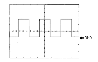
Waveform 1
Table 1. Engine Speed Signal Item
Content
Tester connection
A74-10 (NE) - A73-8 (GND)
Tool setting
5 V/DIV, 2 ms/DIV
Condition
Idling after engine warmed up
Tip:The wavelength becomes shorter as the engine speed increases.