REAR SUSPENSION MEMBER INSTALLATION
PROCEDURE
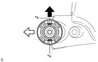
INSTALL REAR SUSPENSION MEMBER FRONT BODY MOUNTING CUSHION (for LH Side)
-
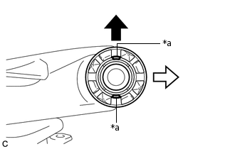
*a
Hole

Front of the Vehicle

Outside of the Vehicle
Temporarily install a new rear suspension member front body mounting cushion so that the holes are positioned longitudinally as shown in the illustration.
-
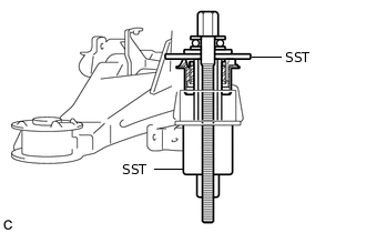
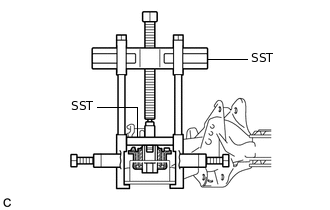
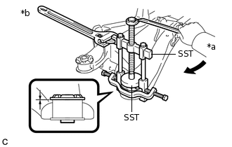
Install SST as shown in the illustration.
09570-24011
09830-10010
09830-01010
09830-01020
09830-01040
09830-01060
Note:Apply a small amount of grease to the threads of SST (center bolt) before use.
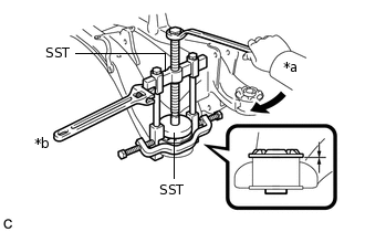
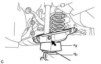
-
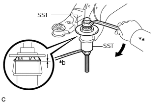
*a
Turn
*b
Hold
Using SST, install the rear suspension member front body mounting cushion until there is no clearance between the rear suspension member sub-assembly and the rear suspension member front body mounting cushion.
09570-24011
09830-10010
09830-01010
09830-01020
09830-01040
09830-01060
-
INSTALL REAR SUSPENSION MEMBER FRONT BODY MOUNTING CUSHION (for RH Side)
Tip:Perform the same procedure as for the LH side.
INSTALL REAR SUSPENSION MEMBER REAR BODY MOUNTING CUSHION LH
-
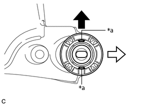
*a
Hole
Front of the Vehicle
Left Side of the Vehicle
Temporarily install a new rear suspension member rear body mounting cushion LH so that the holes are positioned longitudinally as shown in the illustration.
-
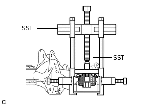
Install SST as shown in the illustration.
09950-40011
09951-04020
09952-04010
09953-04030
09954-04020
09955-04051
09957-04010
09958-04011
09950-60020
09951-00890
09952-06010
Note:Apply a small amount of grease to the threads and tip of SST (center bolt) before use.
-
*a
Turn
*b
Hold
Using SST, install the rear suspension member rear body mounting cushion LH until there is no clearance between the rear suspension member sub-assembly and the rear suspension member rear body mounting cushion LH.
09950-40011
09951-04020
09952-04010
09953-04030
09954-04020
09955-04051
09957-04010
09958-04011
09950-60020
09951-00890
09952-06010
Note:If the rear suspension member sub-assembly is scratched, apply paint to the scratched areas of the rear suspension member sub-assembly.
-
INSTALL REAR SUSPENSION MEMBER REAR BODY MOUNTING CUSHION RH
-
*a
Hole
Front of the Vehicle
Right Side of the Vehicle
Temporarily install a new rear suspension member rear body mounting cushion RH so that the holes are positioned longitudinally as shown in the illustration.
-
Install SST as shown in the illustration.
09950-40011
09951-04020
09952-04010
09953-04030
09954-04020
09955-04051
09957-04010
09958-04011
09950-60020
09951-00890
09952-06010
Note:Apply a small amount of grease to the threads and tip of SST (center bolt) before use.
-
*a
Turn
*b
Hold
Using SST, install the rear suspension member rear body mounting cushion RH until there is no clearance between the rear suspension member sub-assembly and the rear suspension member rear body mounting cushion RH.
09950-40011
09951-04020
09952-04010
09953-04030
09954-04020
09955-04051
09957-04010
09958-04011
09950-60020
09951-00890
09952-06010
Note:If the rear suspension member sub-assembly is scratched, apply paint to the scratched areas of the rear suspension member sub-assembly.
-
INSTALL REAR UPPER CONTROL ARM ASSEMBLY LH
-
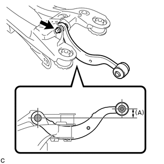
Temporarily install the rear upper control arm assembly LH to the rear suspension member sub-assembly with the bolt and nut.
Note:Because the nut has its own stopper, do not turn the nut. Tighten the bolt with the nut secured.
Insert the bolt with the threaded end facing the rear of the vehicle.
Set the rear upper control arm assembly LH in the tightening position as shown in the illustration.
Reference Length (A)
23.0 mm (0.906 in.)
Fully tighten the bolt in the tightening position.
90 N*m
918 kgf*cm
66 ft.*lbf
Note:Because the nut has its own stopper, do not turn the nut. Tighten the bolt with the nut secured.
-
INSTALL REAR UPPER CONTROL ARM ASSEMBLY RH
Tip:Perform the same procedure as for the LH side.
INSTALL REAR SUSPENSION MEMBER UPPER STOPPER
Install the 2 rear suspension member upper stoppers to the rear suspension member sub-assembly.
Note:Be sure to install the rear suspension member upper stoppers in the correct direction.
INSTALL REAR SUSPENSION MEMBER REAR UPPER STOPPER
Install the 2 rear suspension member rear upper stoppers to the rear suspension member sub-assembly.
Note:Be sure to install the rear suspension member rear upper stoppers in the correct direction.
INSTALL REAR SUSPENSION MEMBER SUB-ASSEMBLY
Support the rear suspension member sub-assembly with an engine lifter using 4 attachments or equivalent tools.
Note:Make sure to secure the rear suspension member sub-assembly to prevent it from dropping.
Use the attachments to keep the rear suspension member sub-assembly level.
The rear suspension member sub-assembly is a heavy component. Make sure that it is supported securely.
Raise the rear suspension member sub-assembly until there is no clearance between the rear suspension member sub-assembly and vehicle body.
Note:When raising the rear suspension member sub-assembly, be careful not to damage the vehicle body or other components installed on the vehicle.
Install the rear suspension member sub-assembly with the rear suspension member lower stoppers LH and RH, 2 rear suspension member rear lower stoppers, 2 bolts, 2 nuts (A) and 2 nuts (B).
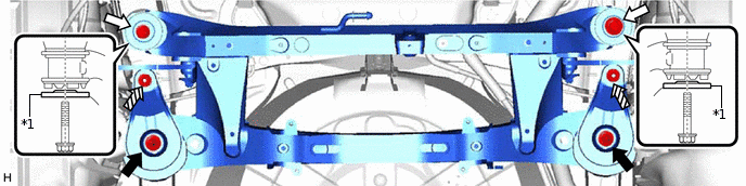
*1
Rear Suspension Member Rear Lower Stopper
-
-
Nut (A)
Bolt

Nut (B)
-
-
Bolt
125 N*m
1275 kgf*cm
92 ft.*lbf
Nut (A)
125 N*m
1275 kgf*cm
92 ft.*lbf
Nut (B)
60.8 N*m
620 kgf*cm
45 ft.*lbf
Note:Be sure to install the rear suspension member sub-assembly with the rear suspension member rear lower stoppers facing in the correct direction as shown in the illustration.
Lower the engine lifter.
INSTALL REAR STABILIZER BAR
INSTALL REAR SUSPENSION MEMBER BRACE LH
INSTALL REAR SUSPENSION MEMBER BRACE RH
Tip:Perform the same procedure as for the LH side.
INSTALL REAR UPPER COIL SPRING INSULATOR LH
INSTALL REAR UPPER COIL SPRING INSULATOR RH
Tip:Perform the same procedure as for the LH side.
INSTALL REAR LOWER COIL SPRING INSULATOR LH
INSTALL REAR LOWER COIL SPRING INSULATOR RH
Tip:Perform the same procedure as for the LH side.
TEMPORARILY INSTALL REAR NO. 2 SUSPENSION ARM ASSEMBLY LH
Temporarily install the rear No. 2 suspension arm assembly LH to the rear suspension member sub-assembly with the bolt and nut.
Note:Because the nut has its own stopper, do not turn the nut. Tighten the bolt with the nut secured.
Insert the bolt with the threaded end facing the front of the vehicle.
-
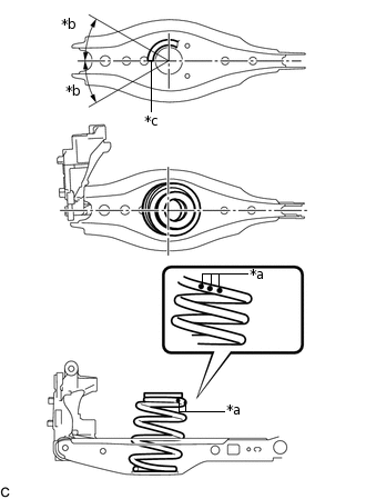
*a
Identification Mark
*b
30° or less
*c
Lower End of Rear Coil Spring
Set the rear coil spring LH to the rear No. 2 suspension arm assembly LH.
Note:Set the rear coil spring so that the identification marks are positioned as shown in the illustration.
Set the rear coil spring so that its lower end is within the range shown in the illustration.
-
*a
Wooden Block
*b
Jack
Using a jack and wooden block, slowly jack up the rear No. 2 suspension arm assembly LH.
CAUTION:Do not jack up the rear No. 2 suspension arm assembly LH too high as the vehicle may fall.
Note:When jacking up the rear No. 2 suspension arm assembly LH, be sure to jack it up slowly.
Make sure to perform this operation with the vehicle kept as low as possible.
Temporarily install the rear No. 2 suspension arm assembly LH and rear coil spring LH with the bolt and nut.
Note:Because the nut has its own stopper, do not turn the nut. Tighten the bolt with the nut secured.
Insert the bolt with the threaded end facing the front of the vehicle.
TEMPORARILY INSTALL REAR NO. 2 SUSPENSION ARM ASSEMBLY RH
Tip:Perform the same procedure as for the LH side.
INSTALL REAR STABILIZER LINK ASSEMBLY LH
INSTALL REAR STABILIZER LINK ASSEMBLY RH
Tip:Perform the same procedure as for the LH side.
INSTALL REAR AXLE ASSEMBLY (for LH Side)
Use a jack and wooden block to keep the rear No. 2 suspension arm assembly LH level.
CAUTION:Do not jack up the rear No. 2 suspension arm assembly LH too high as the vehicle may fall.
Note:When jacking up the rear No. 2 suspension arm assembly LH, be sure to jack it up slowly.
Make sure to perform this operation with the vehicle kept as low as possible.
-
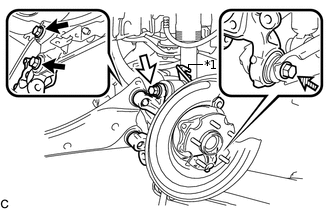
*1
No. 2 Flexible Hose Bracket
Bolt (A)
Bolt (B)
Bolt (C)
Temporarily install the rear axle assembly to the rear No. 2 suspension arm assembly LH with the bolt (C) and nut.
Note:Insert the bolt with the threaded end facing the front of the vehicle.
Because the nut has its own stopper, do not turn the nut. Tighten the bolt with the nut secured.
Temporarily install the rear axle assembly and No. 2 flexible hose bracket to the rear upper control arm assembly with the bolt (B) and nut.
Note:Insert the bolt with the threaded end facing the rear of the vehicle.
Because the nut has its own stopper, do not turn the nut. Tighten the bolt with the nut secured.
Install the rear axle assembly to the rear trailing arm assembly with the 2 bolts (A).
200 N*m
2039 kgf*cm
148 ft.*lbf
Fully tighten the bolt (B) and bolt (C).
90 N*m
918 kgf*cm
66 ft.*lbf
Note:Because the nuts have their own stoppers, do not turn the nuts. Tighten the bolts with the nuts secured.
Slowly lower the rear No. 2 suspension arm assembly LH.
INSTALL REAR AXLE ASSEMBLY (for RH Side)
Tip:Perform the same procedure as for the LH side.
TEMPORARILY INSTALL REAR NO. 1 SUSPENSION ARM ASSEMBLY LH
TEMPORARILY INSTALL REAR NO. 1 SUSPENSION ARM ASSEMBLY RH
Tip:Perform the same procedure as for the LH side.
INSTALL REAR DISC
Install the 2 rear discs.
INSTALL REAR DISC BRAKE CALIPER ASSEMBLY LH
INSTALL REAR DISC BRAKE CALIPER ASSEMBLY RH
Tip:Perform the same procedure as for the LH side.
CONNECT NO. 3 PARKING BRAKE CABLE ASSEMBLY
CONNECT NO. 2 PARKING BRAKE CABLE ASSEMBLY
Tip:Perform the same procedure as for the LH side.
INSTALL PARKING BRAKE LEVER PROTECTOR (for LH Side)
INSTALL PARKING BRAKE LEVER PROTECTOR (for RH Side)
Tip:Perform the same procedure as for the LH side.
INSTALL REAR HEIGHT CONTROL SENSOR SUB-ASSEMBLY (w/ Height Control Sensor)
CONNECT SKID CONTROL SENSOR WIRE LH
CONNECT SKID CONTROL SENSOR WIRE RH
Tip:Perform the same procedure as for the LH side.
ADJUST PARKING BRAKE
INSTALL UPPER CONSOLE PANEL SUB-ASSEMBLY
STABILIZE SUSPENSION
FULLY TIGHTEN REAR NO. 2 SUSPENSION ARM ASSEMBLY LH
FULLY TIGHTEN REAR NO. 2 SUSPENSION ARM ASSEMBLY RH
Tip:Perform the same procedure as for the LH side.
INSTALL REAR FLOOR SIDE MEMBER COVER LH
Install the rear floor side member cover LH with the 2 bolts, nut and 2 clips.
INSTALL REAR FLOOR SIDE MEMBER COVER RH
Install the rear floor side member cover RH with the bolt, nut and clip.
INSTALL REAR SUSPENSION ARM COVER LH
INSTALL REAR SUSPENSION ARM COVER RH
Tip:Perform the same procedure as for the LH side.
INSTALL TAIL EXHAUST PIPE ASSEMBLY
for 1ZR-FAE:Click here
for 8NR-FTS:Click here
INSTALL REAR WHEELS
103 N*m
1050 kgf*cm
76 ft.*lbf
FULLY TIGHTEN REAR NO. 1 SUSPENSION ARM ASSEMBLY LH
FULLY TIGHTEN REAR NO. 1 SUSPENSION ARM ASSEMBLY RH
Tip:Perform the same procedure as for the LH side.
INSPECT AND ADJUST REAR WHEEL ALIGNMENT
CHECK FOR SPEED SENSOR SIGNAL