VACUUM SWITCHING VALVE (w/ EGR Cooler) INSTALLATION
-
INSTALL NO. 2 VACUUM SWITCHING VALVE (for No. 2 EGR)
-
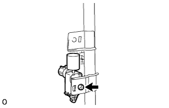
Install the No. 2 VSV to the manifold stay with the screw.
- Torque:
- 3.5 N*m { 36 kgf*cm, 31 in.*lbf }
-
-
INSTALL NO. 1 VACUUM SWITCHING VALVE (for EGR Cut)
-
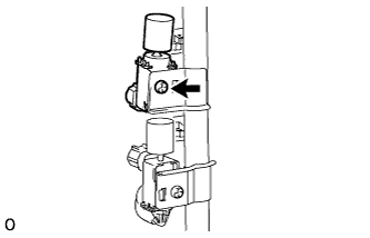
Install the No. 1 VSV to the manifold stay with the screw.
- Torque:
- 3.5 N*m { 36 kgf*cm, 31 in.*lbf }
-
-
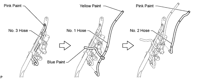
CONNECT NO. 3 VACUUM TRANSMITTING HOSE
-
Connect the vacuum hose to the VSV (for No. 2 EGR valve) shown in the illustration below.
-
-
CONNECT NO. 1 VACUUM TRANSMITTING HOSE
-
Connect the vacuum hose to the VSV (for E-VRV) shown in the illustration below.
-
-
CONNECT NO. 2 VACUUM TRANSMITTING HOSE
-
Connect the vacuum hose to the VSV (for electric EGR control valve) shown in the illustration below.
-
-
INSTALL MANIFOLD STAY WITH VACUUM SWITCHING VALVE
-
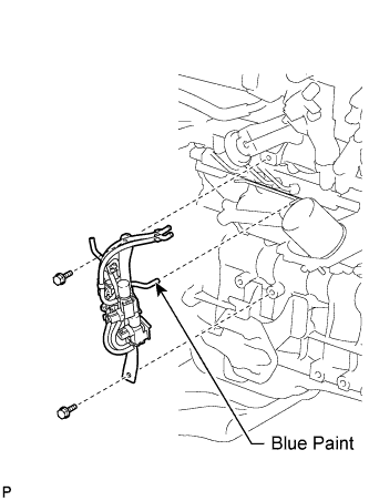
Install the manifold stay with VSV with the 2 bolts, and connect the No. 1 vacuum transmitting hose (color is "Blue") to the No. 2 vacuum transmitting pipe.
- Torque:
- 19 N*m { 194 kgf*cm, 14 ft.*lbf }
Note
Install the vacuum hoses' color matches the connection areas' color.
-
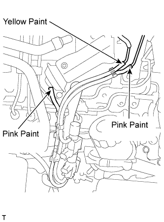
Connect the 3 vacuum hoses.
Note
-
Install the vacuum hoses' color matches the connection areas' color.
-
Make sure the vacuum hoses' color matches the connection areas' color.
-
-
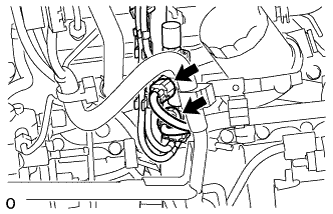
Connect the 2 connectors.
-
-
CONNECT CABLE TO NEGATIVE BATTERY TERMINAL
-
PERFORM INITIALIZATION
-
Perform initialization Click here.
Note
Certain systems need to be initialized after disconnecting and reconnecting the cable from the negative (-) battery terminal.
-