INTERCOOLER INSTALLATION
PROCEDURE
INSTALL INTERCOOLER ASSEMBLY
Install the intercooler assembly to the fan shroud.
INSTALL NO. 1 RADIATOR SUPPORT
Install the No. 1 radiator support to the No. 2 fan shroud and intercooler assembly with the 5 bolts.
7.0 N*m
71 kgf*cm
62 in.*lbf
Install the radiator support cushion to the No. 1 radiator support.
CONNECT NO. 3 AIR HOSE
-
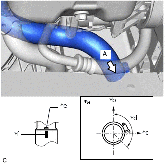
*a
View A
*b
Upper
*c
RH
*d
135° (Hose Clamp Bolt Area)
*e
Stopper
*f
Paint Mark
Connect the No. 3 air hose to the intercooler assembly as shown in the illustration.
Note:Before installation, remove any oil residue from the inside of the pipe and hose.
-
Tighten the hose clamp of the No. 3 air hose on the intercooler assembly side.
6.5 N*m
66 kgf*cm
58 in.*lbf
Note:One minute after tightening the hose clamp, check that residual torque is 3.2 N*m (33 kgf*cm, 28 in.*lbf) or more.
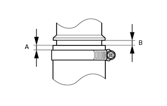
Tip:Push in the No. 3 air hose so that the distance (B) is 0 to 2 mm (0 to 0.0787 in.).
Position the hose clamp so that the distance (A) is 4 to 9 mm (0.157 to 0.354 in.).
-
CONNECT NO. 2 AIR HOSE
-
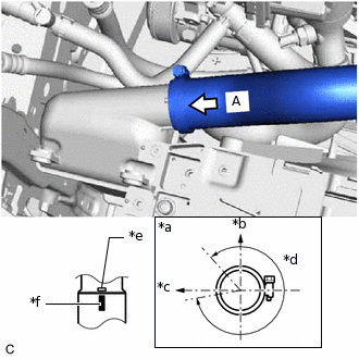
*a
View A
*b
Upper
*c
Front
*d
300° (Hose Clamp Bolt Area)
*e
Stopper
*f
Paint Mark
Connect the No. 2 air hose to the intercooler assembly as shown in the illustration.
Note:Before installation, remove any oil residue from the inside of the pipe and hose.
-
Tighten the hose clamp of the No. 2 air hose on the intercooler assembly side.
6.5 N*m
66 kgf*cm
58 in.*lbf
Note:One minute after tightening the hose clamp, check that residual torque is 3.2 N*m (33 kgf*cm, 28 in.*lbf) or more.
Tip:Push in the No. 2 air hose so that the distance (B) is 0 to 2 mm (0 to 0.0787 in.).
Position the hose clamp so that the distance (A) is 4 to 9 mm (0.157 to 0.354 in.).
-
INSTALL UPPER RADIATOR SUPPORT SUB-ASSEMBLY (except Sedan)
INSTALL UPPER RADIATOR SUPPORT SUB-ASSEMBLY (for Sedan)
INSTALL HOOD LOCK ASSEMBLY (for Sedan)
CONNECT NO. 1 WATER HOSE CLAMP BRACKET (except Sedan)
CONNECT NO. 1 WATER HOSE CLAMP BRACKET (for Sedan)
INSTALL BATTERY
w/o Glow Plug Controller:
w/ Glow Plug Controller:
INSTALL HEADLIGHT ASSEMBLY LH (except Sedan)
INSTALL HEADLIGHT ASSEMBLY LH (for Sedan)
INSTALL HEADLIGHT ASSEMBLY RH
Tip:Use the same procedures for the RH side and LH side.