POWER STEERING SYSTEM TERMINALS OF ECU
CHECK POWER STEERING ECU ASSEMBLY
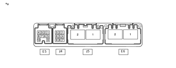
*a
Component without harness connected
(Power Steering ECU Assembly)
-
-
Measure the voltage and resistance according to the value(s) in the table below.
Note:Check if the power steering ECU assembly connectors are securely connected by pulling on them from the backside.
If the EPS warning light is illuminated due to a malfunction, the fail-safe function may cause the voltage of the power steering ECU's terminals to become 0 V.
Terminals No. (Symbol)
Wiring Color
Terminal Description
Condition
Specified Condition
E5-1 (IG) - Body ground
L*1,G*2 - Body ground
IG power source voltage
Ignition switch ON
8 to 16 V
E5-6 (TS) - Body ground
GR - Body ground
Test mode signal
Always
9 to 16 V
E5-7 (CANH) - E5-8 (CANL)
GR - W
CAN communication line
Ignition switch off
54 to 69 Ω
z4-1 (TRQ2) - z4-2 (TRQG)
Y - B
Torque sensor 2 input signal
Engine running and steering wheel not being turned (without load)
2.3 to 2.7 V
Engine running and steering wheel being turned to right with vehicle stopped
1.2 to 2.5 V
Engine running and steering wheel being turned to left with vehicle stopped
2.5 to 3.8 V
z4-2 (TRQG) - Body ground
B - Body ground
Torque sensor ground
Always
Below 1 Ω
z4-8 (TRQV) - z4-2 (TRQG)
R - B
Torque sensor power source
Ignition switch ON
4.5 to 5.5 V
z4-9 (TRQ1) - z4-2 (TRQG)
W - B
Torque sensor 1 input signal
Engine running and steering wheel not being turned (without load)
2.3 to 2.7 V
Engine running and steering wheel being turned to right with vehicle stopped
2.5 to 3.8 V
Engine running and steering wheel being turned to left with vehicle stopped
1.2 to 2.5 V
z5-1 (M1) - Body ground
R - Body ground
Power steering motor assembly output signal 1
Engine running and steering wheel being turned to right
9 to 16 V
Engine running and steering wheel being turned to left
6 to 8 V
z5-2 (M2) - Body ground
B - Body ground
Power steering motor assembly output signal 2
Engine running and steering wheel being turned to right
6 to 8 V
Engine running and steering wheel being turned to left
9 to 16 V
E6-1 (PIG) - Body ground
B - Body ground
Power steering motor assembly power supply input signal
Always
9 to 16 V
E6-2 (PGND) - Body ground
W-B - Body ground
Power ground
Always
Below 1 Ω
If the result is not as specified, the ECU may have a malfunction.
*1: w/ Stop and Start System
*2: w/o Stop and Start System