CONTINUOUSLY VARIABLE TRANSAXLE SYSTEM, Diagnostic DTC:P1585
| DTC Code | DTC Name |
|---|---|
| P1585 | Acceleration Sensor Circuit |
DESCRIPTION
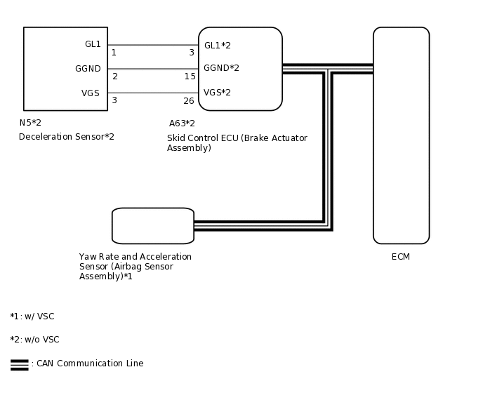
The ECM determines the vehicle inclination based on a signal from the yaw rate and acceleration sensor (airbag sensor assembly)*1 or deceleration sensor*2.
DTC No. |
Detection Item |
DTC Detection Condition |
Trouble Area |
MIL |
Memory |
|---|---|---|---|---|---|
P1585 |
Acceleration Sensor Circuit |
1. Diagnosis Condition 2. Malfunction Status 3. Malfunction Time 4. Other
|
|
- |
DTC stored |
*1: w/ VSC
*2: w/o VSC
WIRING DIAGRAM
CAUTION / NOTICE / HINT
Perform initialization when parts related to the continuously variable transaxle are replaced.
Check that no DTCs are stored after performing initialization.
If a CAN communication DTC is output, perform troubleshooting for that DTC first.
PROCEDURE
CHECK DTC OUTPUT (CAN COMMUNICATION SYSTEM)
Check for DTCs of the CAN communication system.
Result
Proceed to
DTCs are not output
DTCs are output
READ VALUE USING GTS (G SENSOR)
Connect the GTS to the DLC3.
Turn the ignition switch to ON.
Turn the GTS on.
Enter the following menus: Powertrain / Engine and ECT / Data List.
Powertrain > Engine and ECT > Data List
Tester Display
G Sensor
Powertrain > Engine and ECT > Data List
Tester Display
Measurement Item
Range
Normal Condition
Diagnostic Note
G Sensor
Converted output voltage of deceleration sensor
min.: 0 V
max.: 79.998 V
Displays converted voltage of deceleration sensor
Vehicle on level ground: 2.31 V to 2.69 V
Decelerating: 1.88 V to 2.5 V
Accelerating: 2.5 V to 3.11 V
G sensor malfunction: Set to 1.87 V
Communication malfunction: Set to 1.87 V
-
In accordance with the display on the GTS, read the Data List.
Result
Result
Proceed to
Data displayed is as specified under Normal Condition (w/ VSC)
A
Data displayed is as specified under Normal Condition (w/o VSC)
B
Data displayed is not as specified under Normal Condition (w/ VSC)
C
Data displayed is not as specified under Normal Condition (w/o VSC)
D
C REPLACE YAW RATE AND ACCELERATION SENSOR (AIRBAG SENSOR ASSEMBLY)Click here
D CHECK HARNESS AND CONNECTOR (DECELERATION SENSOR - SKID CONTROL ECU)Click here
REPLACE SKID CONTROL ECU (BRAKE ACTUATOR ASSEMBLY)
Replace the skid control ECU (brake actuator assembly).
Result
Proceed to
NEXT
REPLACE YAW RATE AND ACCELERATION SENSOR (AIRBAG SENSOR ASSEMBLY)
Replace the yaw rate and acceleration sensor (airbag sensor assembly).
Result
Proceed to
NEXT
CHECK HARNESS AND CONNECTOR (DECELERATION SENSOR - SKID CONTROL ECU)
Disconnect the N5 deceleration sensor connector.
Disconnect the A63 skid control ECU (brake actuator assembly) connector.
Measure the resistance according to the value(s) in the table below.
Standard Resistance
Tester Connection
Condition
Specified Condition
N5-1 (GL1) - A63-3 (GL1)
Always
Below 1 Ω
N5-2 (GGND) - A63-15 (GGND)
Always
Below 1 Ω
N5-3 (VGS) - A63-26 (VGS)
Always
Below 1 Ω
N5-1 (GL1) or A63-3 (GL1) - Body ground
Always
10 kΩ or higher
N5-2 (GGND) or A63-15 (GGND) - Body ground
Always
10 kΩ or higher
N5-3 (VGS) or A63-26 (VGS) - Body ground
Always
10 kΩ or higher
Result
Proceed to
OK
NG
NG REPAIR OR REPLACE HARNESS OR CONNECTOR
INSPECT DECELERATION SENSOR (POWER SOURCE)
-
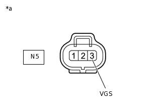
*a
Front view of wire harness connector
(to Deceleration Sensor)
Disconnect the deceleration sensor connector.
Measure the voltage according to the value(s) in the table below.
Standard Voltage
Tester Connection
Switch Condition
Specified Condition
N5-3 (VGS) - Body ground
Ignition switch ON
4.5 to 5.5 V
Result
Proceed to
OK
NG
NG REPLACE SKID CONTROL ECU (BRAKE ACTUATOR ASSEMBLY)Click here
-
INSPECT DECELERATION SENSOR (GL1 VOLTAGE)
-
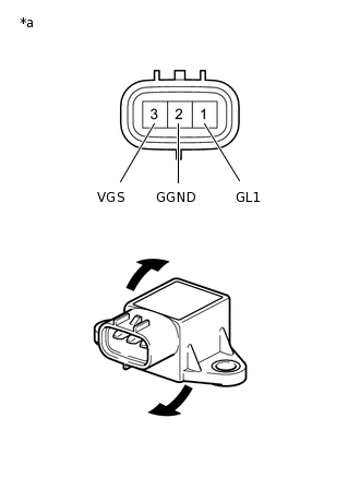
*a
Component without harness connected
(Deceleration Sensor)
Remove the deceleration sensor.
Connect 3 dry cell batteries of 1.5 V in series.
Connect the positive (+) lead of the batteries to terminal 3 (VGS) and the negative (-) lead to terminal 2 (GGND) to apply a voltage of 4.5 V.
Note:Do not apply 6 V or higher to terminals 3 (VGS) and 2 (GGND).
If the sensor is dropped, replace it with a new one.
Measure the voltage according to the value(s) in the table below.
Standard Voltage
Tester Connection
Condition
Specified Condition
1 (GL1) - 2 (GGND)
4.5 V applied to terminals 3 (VGS) and 2 (GGND)
Sensor not tilted
Approx. 2.5 V
1 (GL1) - 2 (GGND)
4.5 V applied to terminals 3 (VGS) and 2 (GGND)
Sensor tilted back and forth
Changes between approx. 0.5 V and 4.5 V
Tip:If the sensor is tilted too much, it may output the wrong value.
Result
Proceed to
OK
NG
OK REPLACE SKID CONTROL ECU (BRAKE ACTUATOR ASSEMBLY)Click here
-
REPLACE DECELERATION SENSOR
Replace the deceleration sensor.
Result
Proceed to
NEXT