REAR AXLE CARRIER INSTALLATION
CAUTION / NOTICE / HINT
Use the same procedure for the RH side and LH side.
The procedure listed below is for the LH side.
PROCEDURE
INSTALL REAR AXLE CARRIER SUB-ASSEMBLY
-
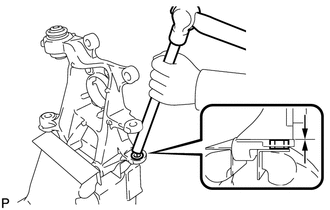
Secure the rear axle carrier sub-assembly between aluminum plates in a vise.
Note:Do not overtighten the vise.
Using a brass bar and a hammer, push out the bushing until it is positioned as shown in the illustration.
Tip:Pushing out the bushing makes it easier to install the rear axle carrier sub-assembly.
Using a jack and wooden block, keep the rear No. 2 suspension arm assembly level.
CAUTION:Do not jack up the rear No. 2 suspension arm assembly too high as the vehicle may fall.
Note:When jacking up the rear No. 2 suspension arm assembly, be sure to jack it up slowly.
Make sure to perform this operation with the vehicle kept as low as possible.
-
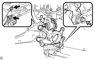
*1
No. 2 Flexible Hose Bracket

Bolt (A)

Bolt (B)

Bolt (C)
Temporarily install the rear axle carrier sub-assembly to the rear No. 2 suspension arm assembly with the bolt (C) and nut.
Note:Insert the bolt with the threaded end facing the front of the vehicle.
Because the nut has its own stopper, do not turn the nut. Tighten the bolt with the nut secured.
Temporarily install the rear axle carrier sub-assembly and No. 2 flexible hose bracket to the rear upper control arm assembly with the bolt (B) and nut.
Note:Insert the bolt with the threaded end facing the rear of the vehicle.
Because the nut has its own stopper, do not turn the nut. Tighten the bolt with the nut secured.
Install the rear axle carrier sub-assembly to the rear trailing arm assembly with the 2 bolts (A).
200 N*m
2039 kgf*cm
148 ft.*lbf
Fully tighten the bolt (B) and bolt (C).
90 N*m
918 kgf*cm
66 ft.*lbf
Note:Because the nuts have their own stoppers, do not turn the nuts. Tighten the bolts with the nuts secured.
Slowly lower the rear No. 2 suspension arm assembly.
-
TEMPORARILY INSTALL REAR NO. 1 SUSPENSION ARM ASSEMBLY
INSTALL REAR AXLE HUB AND BEARING ASSEMBLY
INSPECT REAR AXLE HUB BEARING LOOSENESS
INSPECT REAR AXLE HUB RUNOUT
INSTALL REAR HEIGHT CONTROL SENSOR SUB-ASSEMBLY (w/ Height Control Sensor)
CONNECT SKID CONTROL SENSOR WIRE
INSTALL REAR DISC
INSTALL REAR DISC BRAKE CALIPER ASSEMBLY
CONNECT NO. 3 PARKING BRAKE CABLE ASSEMBLY
INSTALL PARKING BRAKE LEVER PROTECTOR
ADJUST PARKING BRAKE
INSTALL UPPER CONSOLE PANEL SUB-ASSEMBLY
INSTALL REAR FLOOR SIDE MEMBER COVER LH (for LH Side)
INSTALL REAR FLOOR SIDE MEMBER COVER RH (for RH Side)
INSTALL REAR SUSPENSION ARM COVER
INSTALL REAR WHEEL
103 N*m
1050 kgf*cm
76 ft.*lbf
FULLY TIGHTEN REAR NO. 1 SUSPENSION ARM ASSEMBLY
INSPECT AND ADJUST REAR WHEEL ALIGNMENT
CHECK FOR SPEED SENSOR SIGNAL