EXHAUST GAS TEMPERATURE SENSOR INSTALLATION
PROCEDURE
INSTALL EXHAUST GAS TEMPERATURE SENSOR
Note:If the exhaust gas temperature sensor is dropped, replace it with a new one.
Using a 14 mm union nut wrench, install the exhaust gas temperature sensor.
30 N*m
306 kgf*cm
22 ft.*lbf
Note:Use the formula to calculate special torque values for situations where a union nut wrench is click here combined with a torque wrench.
Attach the exhaust gas temperature sensor connector clamp.
INSTALL NO. 2 EXHAUST GAS TEMPERATURE SENSOR
Note:If the No. 2 exhaust gas temperature sensor is dropped, replace it with a new one.
-
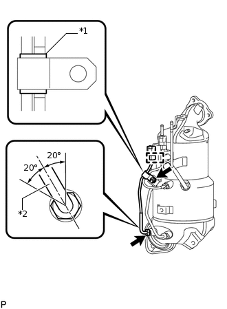
*1
White Tube
*2
Protective Tube
Temporarily install the No. 2 exhaust gas temperature sensor with the union nut.
Attach the No. 2 exhaust gas temperature sensor connector clamp.
Temporarily install the clamp with the nut.
Note:Make sure the clamp is aligned with the white tube of the wire harness as shown in the illustration.
Tighten the nut.
6.4 N*m
65 kgf*cm
57 in.*lbf
Using a 14 mm union nut wrench, tighten the union nut of the No. 2 exhaust gas temperature sensor.
30 N*m
306 kgf*cm
22 ft.*lbf
Note:When tightening the union nut, make sure that the protective tube of the exhaust gas temperature sensor is within the range shown in the illustration.
Use the formula to calculate special torque values for situations where a union nut wrench is click here combined with a torque wrench.
-
INSTALL EXHAUST MANIFOLD CONVERTER SUB-ASSEMBLY
INSTALL NO. 1 MANIFOLD CONVERTER INSULATOR
INSTALL ENGINE ASSEMBLY