POWER OUTLET SOCKET INSTALLATION
PROCEDURE
-
INSTALL NO. 2 POWER OUTLET SOCKET COVER
-
Engage the 2 claws to install the No. 2 power outlet socket cover.
-
-
INSTALL NO. 3 POWER OUTLET SOCKET ASSEMBLY (for LHD)
-
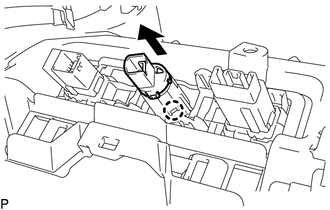
Engage the claw to install the No. 3 power outlet socket assembly as shown in the illustration.
-
-
INSTALL NO. 3 POWER OUTLET SOCKET ASSEMBLY (for RHD)
-
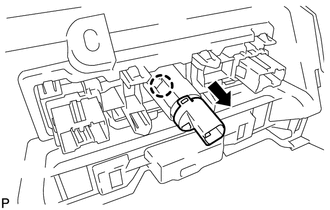
Engage the claw to install the No. 3 power outlet socket assembly as shown in the illustration.
-
-
INSTALL LOWER INSTRUMENT PANEL FINISH PANEL SUB-ASSEMBLY
-
INSTALL INSTRUMENT PANEL BOX ASSEMBLY
-
INSTALL INTEGRATION CONTROL AND PANEL
-
INSTALL CONSOLE BOX ASSEMBLY
-
CONNECT CABLE TO NEGATIVE AUXILIARY BATTERY TERMINAL
Note
When disconnecting the cable, some systems need to be initialized after the cable is reconnected Click here.
-
INSTALL DECK FLOOR BOX RH
-
INSTALL REAR DECK FLOOR BOX
-
INSTALL NO. 1 DECK BOARD
-
INSTALL NO. 2 DECK BOARD
-
INSTALL DECK BOARD ASSEMBLY