AIR CONDITIONING SYSTEM Air Conditioning Control Panel Circuit
DESCRIPTION
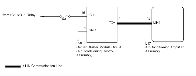
Center cluster module circuit (air conditioning control assembly) switch signals are sent to the air conditioning amplifier assembly via LIN communication.
WIRING DIAGRAM
CAUTION / NOTICE / HINT
Note
Inspect the fuses for circuits related to this system before performing the following inspection procedure.
PROCEDURE
-
CHECK HARNESS AND CONNECTOR (CENTER CLUSTER MODULE CIRCUIT - POWER SOURCE)
-
Disconnect the L20 center cluster module circuit (air conditioning control assembly) connector.
-
Measure the voltage according to the value(s) in the table below.
Standard Voltage Tester Connection Condition Specified Condition L20-16 (IG+) - Body ground Power switch off Below 1 V Power switch on (IG) 11 to 14 V
NG 
REPAIR OR REPLACE HARNESS OR CONNECTOR
OK 
-
-
CHECK HARNESS AND CONNECTOR (CENTER CLUSTER MODULE CIRCUIT - GROUND)
-
Measure the resistance according to the value(s) in the table below.
Standard Resistance Tester Connection Condition Specified Condition L20-1 (GND) - Body ground Always Below 1 Ω
NG
REPAIR OR REPLACE HARNESS OR CONNECTOR
OK
-
-
CHECK HARNESS AND CONNECTOR (AIR CONDITIONING AMPLIFIER - CENTER CLUSTER MODULE CIRCUIT)
-
Disconnect the L17 air conditioning amplifier assembly connector.
-
Measure the resistance according to the value(s) in the table below.
Standard Resistance Tester Connection Condition Specified Condition L20-3 (TX+) - L17-37 (LIN1) Always Below 1 Ω L20-3 (TX+) - Body ground Always 10 kΩ or higher
NG
REPAIR OR REPLACE HARNESS OR CONNECTOR
OK
-
-
REPLACE CENTER CLUSTER MODULE CIRCUIT (AIR CONDITIONING CONTROL ASSEMBLY)
-
Replace the center cluster module circuit (air conditioning control assembly) with a new or known good one Click here.
OK The center cluster module circuit (air conditioning control assembly) operation returns to normal.
OK
END (CENTER CLUSTER MODULE CIRCUIT WAS DEFECTIVE)
NG
PROCEED TO NEXT SUSPECTED AREA SHOWN IN PROBLEM SYMPTOMS TABLE Click here
-