СИСТЕМА SFI, Diagnostic DTC:P0724
| DTC Code | DTC Name |
|---|---|
| P0724 | Brake Switch "B" Circuit High |
DESCRIPTION
The stop light switch assembly is part of a duplex system that transmits two signals: STP and ST1-. These two signals are used by the ECM to monitor whether or not the brake system is working properly. This DTC indicates that the stop light switch assembly is remaining on. When the stop light switch assembly remains on during "STOP and GO" driving, the ECM interprets this as a fault in the stop light switch assembly. The ECM will illuminate the MIL and store this DTC.
| DTC No. | Detection Item | DTC Detection Condition | Trouble Area | MIL | Memory |
|---|---|---|---|---|---|
| P0724 | Brake Switch "B" Circuit High | The stop light switch assembly remains on even when the vehicle repeats 5 cycles of STOP (less than 3 km/h [1.86 mph]) and GO (30 km/h [18.65 mph] or more) (2 trip detection logic). |
|
Comes on | DTC stored |
MONITOR DESCRIPTION
This DTC indicates that the stop light switch assembly is remaining on. When the stop light switch assembly remains on during "STOP and GO" driving, the ECM interprets this as a malfunction of the stop light switch assembly, illuminates the MIL and stores this DTC. The vehicle must STOP (less than 3 km/h [1.86 mph]) and GO (30 km/h [18.65 mph] or more) 5 times during 2 driving cycles, in order to detect a malfunction.
MONITOR STRATEGY
| Required Sensors/Components | Stop light switch assembly |
| Frequency of Operation | Continuous |
CONFIRMATION DRIVING PATTERN
-
Connect the GTS to the DLC3.
-
Turn the engine switch on (IG) and turn the GTS on.
-
Clear the DTCs (even if no DTCs are stored, perform the clear DTC procedure).
-
Turn the engine switch off and wait for at least 30 seconds.
-
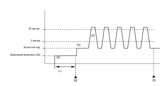
Turn the engine switch on (IG) and turn the GTS on [A].
-
Wait 5 seconds.
-
Enter the following menus: Powertrain / Engine and ECT / Trouble Codes [B].
-
Read the pending DTCs.
Tech Tips
-
If a pending DTC is output, the system is malfunctioning.
-
If a pending DTC is not output, perform the following procedure.
-
-
Enter the following menus: Powertrain / Engine and ECT / Utility / All Readiness.
-
Input the DTC: P0724.
-
Check the DTC judgment result.
GTS Display Description NORMAL
-
DTC judgment completed
-
System normal
ABNORMAL
-
DTC judgment completed
-
System abnormal
INCOMPLETE
-
DTC judgment not completed
-
Perform driving pattern after confirming DTC enabling conditions
N/A
-
Unable to perform DTC judgment
-
Number of DTCs which do not fulfill DTC preconditions has reached ECU memory limit
Tech Tips
-
If the judgment result shows NORMAL, the system is normal.
-
If the judgment result shows ABNORMAL, the system has a malfunction.
-
If the judgment result shows INCOMPLETE or N/A, perform steps [C] through [E].
-
-
Start the engine [C].
-
Accelerate the vehicle to 30 km/h (18.65 mph) or more, depress the brake pedal and decelerate the vehicle to 3 km/h (1.86 mph) or less [D]. Repeat step [D] 5 times.
CAUTION:
When performing the confirmation driving pattern, obey all speed limits and traffic laws.
-
Enter the following menus: Powertrain / Engine and ECT / Trouble Codes [E].
-
Read the pending DTCs.
Tech Tips
-
If a pending DTC is output, the system is malfunctioning.
-
If a pending DTC is not output, perform the following procedure.
-
-
Enter the following menus: Powertrain / Engine and ECT / Utility / All Readiness.
-
Input the DTC: P0724.
-
Check the DTC judgment result.
GTS Display Description NORMAL
-
DTC judgment completed
-
System normal
ABNORMAL
-
DTC judgment completed
-
System abnormal
INCOMPLETE
-
DTC judgment not completed
-
Perform driving pattern after confirming DTC enabling conditions
N/A
-
Unable to perform DTC judgment
-
Number of DTCs which do not fulfill DTC preconditions has reached ECU memory limit
Tech Tips
-
If the judgment result shows NORMAL, the system is normal.
-
If the judgment result shows ABNORMAL, the system has a malfunction.
-
If the judgment result shows INCOMPLETE or N/A, perform the Confirmation Driving Pattern and check the DTC judgment result again.
-
CAUTION / NOTICE / HINT
Note
Inspect the fuses for circuits related to this system before performing the following procedure.
Tech Tips
-
Using the GTS, the Data List item "Stop Light Switch" and "ST1" can be read.
-
Read freeze frame data using the GTS. The ECM records vehicle and driving condition information as freeze frame data the moment a DTC is stored. When troubleshooting, freeze frame data can help determine if the vehicle was moving or stationary, if the engine was warmed up or not, if the air fuel ratio was lean or rich, and other data from the time the malfunction occurred.
PROCEDURE
-
READ VALUE USING GTS (STOP LIGHT SWITCH)
-
Connect the GTS to the DLC3.
-
Turn the engine switch on (IG).
-
Turn the GTS on.
-
Enter the following menus: Powertrain / Engine and ECT / Data List / All Data / Stop Light Switch.
Powertrain > Engine > Data ListTester Display Stop Light Switch -
Read the values displayed on the GTS.
OK GTS Display Measurement Item/Range (display) Normal Condition Stop Light Switch Stop light switch status: ON or OFF
-
ON: Brake pedal depressed
-
OFF: Brake pedal released
Result Proceed to OK NG -
OK 
CHECK FOR INTERMITTENT PROBLEMS Click here
NG 
-
-
CHECK STOP LIGHT SWITCH ASSEMBLY INSTALLATION
-
Check the stop light switch assembly installation.
OK Stop light switch assembly is installed correctly. Result Proceed to OK NG
NG
SECURELY REINSTALL STOP LIGHT SWITCH ASSEMBLY Click here
OK
-
-
INSPECT STOP LIGHT SWITCH ASSEMBLY
-
Inspect the stop light switch assembly.
Result Proceed to OK NG
NG
REPLACE STOP LIGHT SWITCH ASSEMBLY Click here
OK
-
-
CHECK TERMINAL VOLTAGE (STP VOLTAGE)
-
Disconnect the ECM connector.
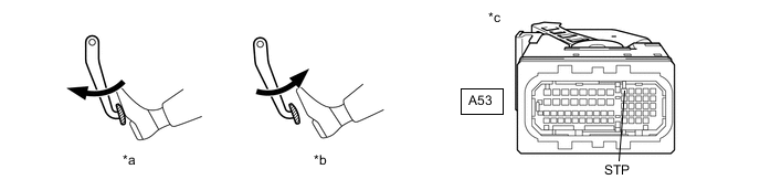
*a Brake Pedal Depressed *b Brake Pedal Released *c Front view of wire harness connector
(to ECM)
- - -
Measure the voltage according to the value(s) in the table below.
Standard Voltage Tester Connection Brake Pedal Condition Specified Condition A53-9 (STP) - Body ground Released Below 1.5 V Depressed 7.5 to 14 V Result Proceed to OK NG
OK
REPLACE ECM Click here
NG
REPAIR OR REPLACE HARNESS OR CONNECTOR (STOP LIGHT SWITCH ASSEMBLY - ECM)
-