BRAKE BOOSTER(for RHD) INSTALLATION
PROCEDURE
-
INSTALL BRAKE BOOSTER GASKET
-
Install a new brake booster gasket to the brake booster assembly.
-
-
INSTALL BRAKE BOOSTER ASSEMBLY
-
While pushing the suction pipe sub-assembly toward the bottom of the vehicle, temporarily install the brake booster assembly to the vehicle.
Note
-
Do not apply excessive force to the suction pipe sub-assembly.
-
Do not apply excessive force to the brake lines or refrigerant lines.
-
-
Return the front No. 1 brake tube, front No. 2 brake tube and front No. 3 brake tube to their original positions.
Note
Do not apply excessive force to the brake tubes.
-
Temporarily install the lock nut and brake master cylinder push rod clevis to the brake booster assembly.
Note
Fully tighten the lock nut when adjusting the brake pedal height.
-
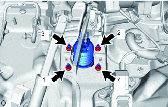
Install the 4 nuts to secure the brake booster assembly.
- Torque:
- 12.7 N*m { 130 kgf*cm, 9 ft.*lbf }
Note
Tighten the 4 nuts in the order shown in the illustration.
-
Remove the protective tape.
-
w/ Stop and Start System:
Connect the vacuum sensor assembly connector to the vacuum sensor assembly.
-
w/ Vacuum Warning Switch:
-
Connect the vacuum warning switch connector to the vacuum warning switch assembly.
-
-
-
SEPARATE SUCTION PIPE SUB-ASSEMBLY (for TMMT Made)
-
Install the suction pipe sub-assembly to the engine mounting sub-assembly and vehicle body with the 2 nuts.
- Torque:
- 5.4 N*m { 55 kgf*cm, 48 in.*lbf }
-
-
INSTALL SUCTION PIPE SUB-ASSEMBLY (for TMC Made)
-
Engage the 2 clamps to install the suction pipe sub-assembly to the piping clamp.
-
-
INSTALL BRAKE TUBE
-
Engage the 3 clamps to install a new No. 1 brake tube clamp to the front No. 1 brake tube, front No. 2 brake tube and front No. 3 brake tube.
-
Engage the 2 clamps to install 2 new No. 2 brake tube clamps to the vehicle body.
-
Engage the 6 clamps to install the 2 No. 2 brake tube clmaps to the front No. 1 brake tube, front No. 2 brake tube and front No. 3 brake tube.
-
for Manual Transaxle:
-
Engage the 2 clamps to install the clutch tube to the 2 brake tube clamps.
-
-
*a Torque Wrench Fulcrum Length Engage the 11 clamps to install the 2 new No. 1 brake tube clmaps to the front No. 1 brake tube, front No. 2 brake tube, front No. 3 brake tube and front No. 5 brake tube.
-
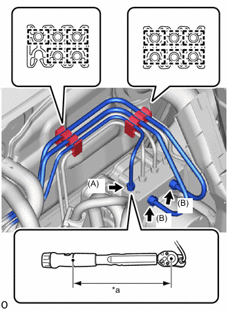
Temporarily install front No. 1 brake tube, front No. 2 brake tube and front No. 3 brake tube to the correct position on the brake actuator assembly.
-
Using a 10 mm and 12 mm union nut wrench, tighten the front No. 1 brake tube, front No. 2 brake tube and front No. 3 brake tube.
- Torque:
- Specified tightening torque (A)
- 15.2 N*m { 155 kgf*cm, 11 ft.*lbf }
- Specified tightening torque (B)
- 19.5 N*m { 199 kgf*cm, 14 ft.*lbf }
Note
-
Do not kink or damage the brake tubes.
-
Do not allow the brake tubes to twist or interfere with other parts or the vehicle body during tightening.
-
Do not allow any foreign matter such as dirt or dust to enter the brake tubes from the connecting parts.
Tech Tips
-
Calculate the torque wrench reading when changing the fulcrum length of the torque wrench.
-
When using a union nut wrench (fulcrum length of 22 mm (0.866 in.)) + torque wrench (fulcrum length of 162 mm (6.38 in.)) (A): 13.4 N*m (137 kgf*cm, 10 ft.*lbf)
-
When using a union nut wrench (fulcrum length of 20 mm (0.787 in.)) + torque wrench (fulcrum length of 162 mm (6.38 in.)) (B): 17.4 N*m (177 kgf*cm, 13 ft.*lbf)
-
Temporarily install front No. 3 brake tube to the front flexible hose.
-
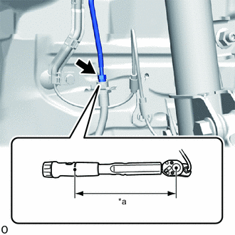
*a Torque Wrench Fulcrum Length Using a 10 mm union nut wrench, tighten the front No. 3 brake tube.
- Torque:
- Specified tightening torque
- 15.2 N*m { 155 kgf*cm, 11 ft.*lbf }
Note
-
Do not kink or damage the brake tubes.
-
Do not allow the brake tubes to twist or interfere with other parts or the vehicle body during tightening.
-
Do not allow any foreign matter such as dirt or dust to enter the brake tubes from the connecting parts.
Tech Tips
-
Calculate the torque wrench reading when changing the fulcrum length of the torque wrench.
-
When using a union nut wrench (fulcrum length of 22 mm (0.866 in.)) + torque wrench (fulcrum length of 162 mm (6.38 in.)): 13.4 N*m (137 kgf*cm, 10 ft.*lbf)
-
-
CONNECT CHECK VALVE TO CONNECTOR TUBE HOSE
-
Connect the check valve to connector tube hose to the brake booster assembly and slide the clip to secure it.
-
-
INSTALL VACUUM HOSE ASSEMBLY
-
Install the vacuum hose assembly to the vehicle body with the 2 nuts.
- Torque:
- 5.4 N*m { 55 kgf*cm, 48 in.*lbf }
-
-
INSTALL DASH PANEL HEAT INSULATOR
-
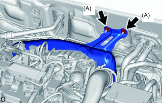
Temporarily install dash panel heat insulator to the vehicle body with the 2 nuts (A).
-
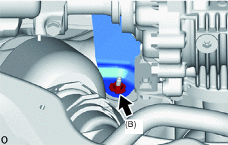
Install the nut (B).
- Torque:
- 5.0 N*m { 51 kgf*cm, 44 in.*lbf }
-
Tighten the 2 nuts (A).
- Torque:
- 5.0 N*m { 51 kgf*cm, 44 in.*lbf }
-
-
INSTALL NO. 1 ENGINE UNDER COVER
-
INSTALL PUSH ROD PIN
-
INSTALL BRAKE PEDAL RETURN SPRING
-
INSTALL CLUTCH MASTER CYLINDER ASSEMBLY (for Manual Transaxle)
-
INSTALL BRAKE MASTER CYLINDER SUB-ASSEMBLY
-
INSTALL NO. 2 CYLINDER HEAD COVER
-
INSPECT AND ADJUST BRAKE PEDAL