NAVIGATION SYSTEM(for Radio and Display Type), Diagnostic DTC:B158F
| DTC Code | DTC Name |
|---|---|
| B158F | AV Signal Stoppage (Low Battery Voltage) |
DESCRIPTION
This DTC is stored when a video or audio signal is interrupted due to battery voltage input to the radio and display receiver assembly dropping temporarily.
DTC No. |
Detection Item |
DTC Detection Condition |
Trouble Area |
|---|---|---|---|
B158F |
AV Signal Stoppage (Low Battery Voltage) |
A video or audio signal is interrupted when the battery voltage drops. |
|
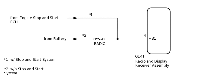
WIRING DIAGRAM
CAUTION / NOTICE / HINT
Inspect the fuses for circuits related to this system before performing the following procedure.
Check that the wire harness is properly installed and does not have any sharp bends, pinching or loose connections.
PROCEDURE
CHECK VEHICLE SIGNAL (OPERATION CHECK)
-
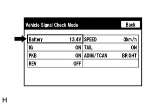
Enter the "Vehicle Signal Check Mode" screen. Refer to Check Vehicle Signal in Operation Check.
Check that the battery voltage.
Standard voltage
11 to 14 V
Tip:This display is updated once per second. As a result, it is normal for the display to lag behind the actual switch operation.
Result
Proceed to
OK
NG
NG CHECK HARNESS AND CONNECTOR (RADIO AND DISPLAY RECEIVER ASSEMBLY POWER SOURCE)Click here
-
CHECK FOR DTC
Clear the DTCs.
Body Electrical > Navigation System > Clear DTCs
Check for DTCs.
Body Electrical > Navigation System > Trouble Codes
OK
No DTCs are output.
Result
Proceed to
OK
NG
CHECK HARNESS AND CONNECTOR (RADIO AND DISPLAY RECEIVER ASSEMBLY POWER SOURCE)
-
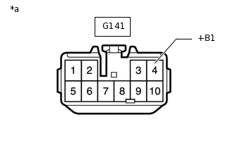
*a
Front view of wire harness connector
(to Radio and Display Receiver Assembly)
Disconnect the radio and display receiver assembly connector.
Measure the voltage according to the value(s) in the table below.
Standard Voltage
Tester Connection
Condition
Specified Condition
G141-4 (+B1) - Body ground*1
Always
9.5 to 14 V
G141-4 (+B1) - Body ground*2
Always
11 to 14 V
*1: w/ Stop and Start System
*2: w/o Stop and Start System
Result
Proceed to
OK
NG
NG REPAIR OR REPLACE HARNESS OR CONNECTOR
-