TOYOTA PARKING ASSIST-SENSOR SYSTEM(except Hatchback) Clearance Warning Buzzer Circuit
| DTC Code | DTC Name |
|---|---|
| Clearance Warning Buzzer Circuit |
DESCRIPTION
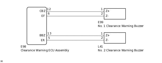
This circuit consists of the No. 1 clearance warning buzzer, No. 2 clearance warning buzzer and clearance warning ECU assembly. An ECU-excited type buzzer is used. The ECU operates the buzzers using a sound pattern that changes depending on the distance to the obstacle.
WIRING DIAGRAM
CAUTION / NOTICE / HINT
Depending on the parts that are replaced during vehicle inspection or maintenance, performing initialization may be needed. Refer to Initialization.
PROCEDURE
CHECK CLEARANCE WARNING BUZZER
Check the operation of the No. 1 and No. 2 clearance warning buzzers.
Result
Result
Proceed to
Buzzer does not sound when an obstacle is detected in front or at the rear of the vehicle.
A
Buzzer does not sound only when an obstacle is detected in front of the vehicle.
B
Buzzer does not sound only when an obstacle is detected at the rear of the vehicle.
C
C PERFORM ACTIVE TEST USING GTSClick here
PERFORM ACTIVE TEST USING GTS
Connect the GTS to the DLC3.
Turn the ignition switch to ON.
Turn the GTS on.
Enter the following menus: Body Electrical / Clearance Sonar/Simple-IPA. / Active Test.
Check that the front buzzer operates by performing the Active Test.
Body Electrical > Clearance Sonar / Simple-IPA. > Active Test
Tester Display
Measurement Item
Control Range
Diagnostic Note
Front Buzzer
No. 1 clearance warning buzzer
Stop or Operate
Confirm that the vehicle is stopped and the ignition switch is ON
Body Electrical > Clearance Sonar / Simple-IPA. > Active Test
Tester Display
Front Buzzer
OK
The No. 1 clearance warning buzzer sounds.
Result
Proceed to
OK
NG
CHECK HARNESS AND CONNECTOR (CLEARANCE WARNING ECU ASSEMBLY - NO. 1 CLEARANCE WARNING BUZZER)
Disconnect the E98 clearance warning ECU assembly connector.
Disconnect the E99 No. 1 clearance warning buzzer connector.
Measure the resistance according to the value(s) in the table below.
Standard Resistance
Tester Connection
Condition
Specified Condition
E98-12 (CBZ) - E99-1 (Z+)
Always
Below 1 Ω
E98-6 (EF) - E99-2 (Z-)
Always
Below 1 Ω
E98-12 (CBZ) - Body ground
Always
10 kΩ or higher
E98-6 (EF) - Body ground
Always
10 kΩ or higher
Result
Proceed to
OK
NG
NG REPAIR OR REPLACE HARNESS OR CONNECTOR
REPLACE NO. 1 CLEARANCE WARNING BUZZER
Replace the No. 1 clearance warning buzzer with a new or known good one.
for Wagon:Click here
for Sedan:Click here
Result
Proceed to
NEXT
PERFORM ACTIVE TEST USING GTS
Connect the GTS to the DLC3.
Turn the ignition switch to ON.
Turn the GTS on.
Enter the following menus: Body Electrical / Clearance Sonar/Simple-IPA. / Active Test.
Check that the front buzzer operates by performing the Active Test.
Body Electrical > Clearance Sonar / Simple-IPA. > Active Test
Tester Display
Measurement Item
Control Range
Diagnostic Note
Front Buzzer
No. 1 clearance warning buzzer
Stop or Operate
Confirm that the vehicle is stopped and the ignition switch is ON
Body Electrical > Clearance Sonar / Simple-IPA. > Active Test
Tester Display
Front Buzzer
OK
The No. 1 clearance warning buzzer sounds.
Result
Result
Proceed to
OK
A
NG
B
A END (NO. 1 CLEARANCE WARNING BUZZER WAS DEFECTIVE)
B REPLACE CLEARANCE WARNING ECU ASSEMBLY
PERFORM ACTIVE TEST USING GTS
Connect the GTS to the DLC3.
Turn the ignition switch to ON.
Turn the GTS on.
Enter the following menus: Body Electrical / Clearance Sonar/Simple-IPA. / Active Test.
Check that the rear buzzer operates by performing the Active Test.
Body Electrical > Clearance Sonar / Simple-IPA. > Active Test
Tester Display
Measurement Item
Control Range
Diagnostic Note
Rear Buzzer
No. 2 clearance warning buzzer
Stop or Operate
Confirm that the vehicle is stopped and the ignition switch is ON
Body Electrical > Clearance Sonar / Simple-IPA. > Active Test
Tester Display
Rear Buzzer
OK
The No. 2 clearance warning buzzer sounds.
Result
Proceed to
OK
NG
CHECK HARNESS AND CONNECTOR (CLEARANCE WARNING ECU ASSEMBLY - NO. 2 CLEARANCE WARNING BUZZER)
Disconnect the E98 clearance warning ECU assembly connector.
Disconnect the L41 No. 2 clearance warning buzzer connector.
Measure the resistance according to the value(s) in the table below.
Standard Resistance
Tester Connection
Condition
Specified Condition
E98-13 (BBZ) - L41-1 (Z+)
Always
Below 1 Ω
E98-5 (ER) - L41-2 (Z-)
Always
Below 1 Ω
E98-13 (BBZ) - Body ground
Always
10 kΩ or higher
E98-5 (ER) - Body ground
Always
10 kΩ or higher
Result
Proceed to
OK
NG
NG REPAIR OR REPLACE HARNESS OR CONNECTOR
REPLACE NO. 2 CLEARANCE WARNING BUZZER
Replace the No. 2 clearance warning buzzer with a new or known good one.
for Wagon:Click here
for Sedan:Click here
Result
Proceed to
NEXT
PERFORM ACTIVE TEST USING GTS
Connect the GTS to the DLC3.
Turn the ignition switch to ON.
Turn the GTS on.
Enter the following menus: Body Electrical / Clearance Sonar/Simple-IPA. / Active Test.
Check that the rear buzzer operates by performing the Active Test.
Body Electrical > Clearance Sonar / Simple-IPA. > Active Test
Tester Display
Measurement Item
Control Range
Diagnostic Note
Rear Buzzer
No. 2 clearance warning buzzer
Stop or Operate
Confirm that the vehicle is stopped and the ignition switch is ON
Body Electrical > Clearance Sonar / Simple-IPA. > Active Test
Tester Display
Rear Buzzer
OK
The No. 2 clearance warning buzzer sounds.
Result
Result
Proceed to
OK
A
NG
B
A END (NO. 2 CLEARANCE WARNING BUZZER WAS DEFECTIVE)
B REPLACE CLEARANCE WARNING ECU ASSEMBLY