BLOWER UNIT REASSEMBLY
CAUTION / NOTICE / HINT
Tech Tips
-
Use the same procedure for RHD and LHD vehicles.
-
The procedure listed below is for LHD vehicles.
PROCEDURE
-
INSTALL NO. 1 BLOWER DAMPER SERVO SUB-ASSEMBLY
-
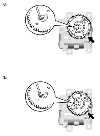
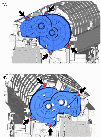
*A for LHD *B for RHD Using a thin-bladed screwdriver, detach the claw and remove the No. 1 blower damper servo sub-assembly gear as shown in the illustration.
-
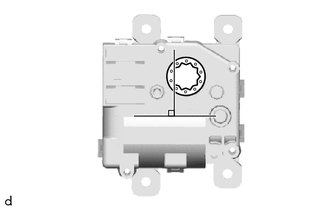
Align the No. 1 blower damper servo sub-assembly with the standard position, attach the claw and install the gear as shown in the illustration.
Note
Attach the claw securely.
-
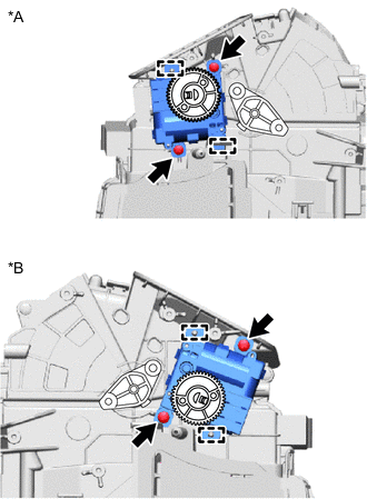
*A for LHD *B for RHD Attach the guide.
-
Install the No. 1 blower damper servo sub-assembly with the 2 screws.
-
for LHD:
-
With the gears of the cover plate and No. 1 blower damper servo sub-assembly aligned in the standard position as shown in the illustration, attach the cover plate to the guide while moving the lever so that the point of engagement on the upper fan door lever and the point of engagement of the lower fan door lever enter the check holes.
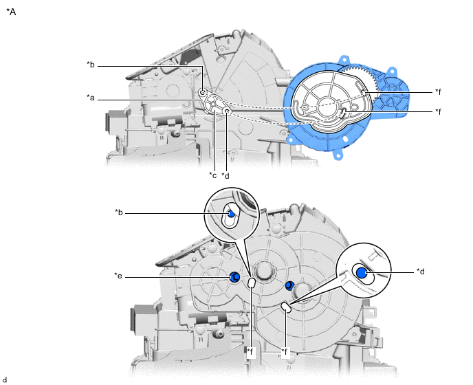
*A for LHD - - *a Upper Fan Door Lever *b Fitting Surface of Upper Fan Door Lever *c Lower Fan Door Lever *d Fitting Surface of Lower Fan Door Lever *e Gears of cover plate and No. 1 blower damper servo sub-assembly aligned in standard position *f Check Hole
-
-
for RHD:
-
With the gears of the cover plate and No. 1 blower damper servo sub-assembly aligned in the standard position as shown in the illustration, attach the cover plate to the guide while moving the lever so that the point of engagement on the upper fan door lever and the point of engagement of the lower fan door lever enter the check holes.
Tech Tips
The upper fan door lever engagement cannot be checked from point of engagement with the check hole on the front surface of the cover plate. Therefore, look through the gap to check the engagement.
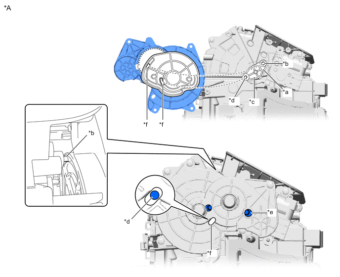
*A for RHD - - *a Upper Fan Door Lever *b Fitting Surface of Upper Fan Door Lever *c Lower Fan Door Lever *d Fitting Surface of Lower Fan Door Lever *e Gears of cover plate and No. 1 blower damper servo sub-assembly aligned in standard position *f Check Hole
-
-
*A for LHD *B for RHD Install the cover plate with the 4 screws.
-
-
INSTALL NO. 2 COOLING UNIT PACKING
-
When reusing the blower motor with fan sub-assembly:
-
-
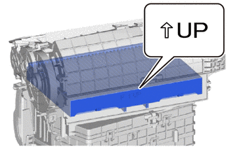
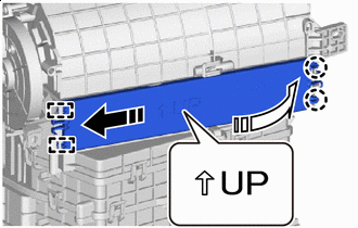
INSTALL BLOWER MOTOR WITH FAN SUB-ASSEMBLY
-
Install the blower motor with fan sub-assembly with the 3 screws.
-
-
INSTALL SPRING NUT
-
Install the 4 spring nuts.
-
-
INSTALL CLEAN AIR FILTER
-
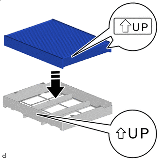

Insert Straight Install the clean air filter to the air filter case.
Note
Align with the direction of the UP mark and install.
-
Install it to the guide.
-
-
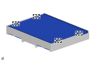
INSTALL AIR FILTER CASE
-
Insert the air filter case.
Note
Insert so that the UP mark arrow is pointing upwards.
-
-
INSTALL AIR FILTER COVER PLATE
-
Install in this Direction 
Rotate in this Direction Insert the guide in the direction indicated by the arrow shown in the illustration.
-
Rotate in the direction indicated by the arrow shown in the illustration, attach the claw and install the air filter cover plate in the order shown in the illustration.
Note
Install it with the arrow of the UP mark facing upward.
-
-
INSTALL NO. 1 COOLING UNIT PACKING
-
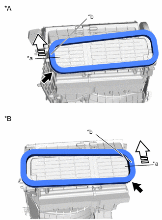
*A for LHD *B for RHD *a Reference Line *b Wrap Portion Apply in this Direction Remove the peeling paper on a new No. 1 cooling unit packing trying not to touch the adhesional surface and install it to the blower assembly.
Note
-
Check that any remaining No. 1 cooling unit packing has been completely removed from the blower assembly.
-
Attach so that there are no gaps in the entire circumference.
-
Start application from the reference line and follow the direction of the arrow.
-
Wrap and attach the No. 1 cooling unit packing. Do not cut it.
-
-
-
INSTALL NO. 1 COOLER UNIT DRAIN HOSE
-
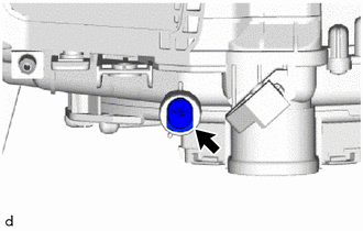
Install the No. 1 cooler unit drain hose.
-