CAN COMMUNICATION SYSTEM SYSTEM DIAGRAM
OVERALL CAN BUS DIAGRAM
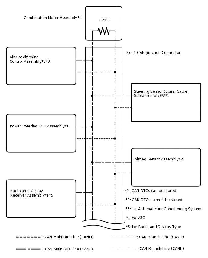
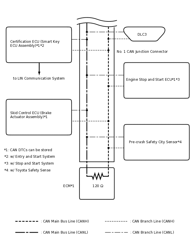
The CAN communication system is composed of 1 bus.
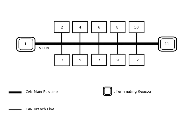
1
ECM
2
Skid Control ECU (Brake Actuator Assembly)
3
Certification ECU (Smart Key ECU Assembly)
(w/ Entry and Start System)
4
Engine Stop and Start ECU
(w/ Stop and Start System)
5
DLC3
6
Airbag Sensor Assembly
7
Air Conditioning Control Assembly
(for Automatic Air Conditioning System)
8
Steering Sensor (Spiral Cable Sub-assembly)
(w/ VSC)
9
Power Steering ECU Assembly
10
Radio and Display Receiver Assembly
(for Radio and Display Type)
11
Combination Meter Assembly
12
Pre-crash Safety City Sensor
(w/ Toyota Safety Sense)
Tip:Refer to the following bus wiring diagrams for details.
V BUS
 Tip:
Tip:The CAN communication system connects to other networks via ECUs that function as a gateway.