AUTOMATIC TRANSMISSION UNIT(for 8GR-FKS) INSPECTION

PROCEDURE
-
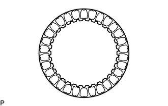
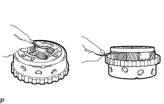
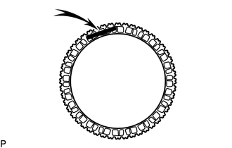
INSPECT TRANSMISSION DRIVE CHAIN
-
Check the transmission drive chain for wear or damage.
If any of the following defects is found, replace the transmission drive chain.
-
-
INSPECT OIL PUMP DRIVE SHAFT SUB-ASSEMBLY
-
Check the oil pump drive shaft sub-assembly for wear or damage.
If any of the following defects is found, replace the oil pump drive shaft sub-assembly.
-
-
INSPECT DRIVE SPROCKET
-
Check the drive sprocket for wear or damage.
If any of the following defects is found, replace the drive sprocket.
-
-
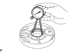
INSPECT FRONT OIL PUMP ASSEMBLY
-
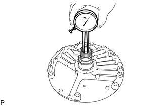
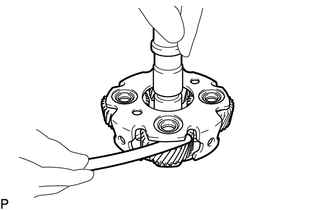
Using a caliper gauge, measure the inside diameter of the front oil pump assembly bushing.
Standard Inside Diameter 25.900 to 25.926 mm (1.0197 to 1.0207 in.) If the inside diameter is not as specified, replace the front oil pump assembly.
-
-
INSPECT NO. 1 BRAKE DISC
-
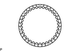
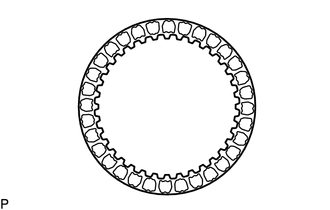
Check if the contact surfaces of the No. 1 brake discs, No. 1 brake plates and No. 1 brake flange are worn or burnt.
If necessary, replace them.
Note
-
If the lining of any No. 1 brake disc is peeled or discolored, or even if part of a groove is damaged, replace all of the No. 1 brake discs.
-
Before installing new No. 1 brake discs, soak them in ATF for at least 15 minutes.
-
-
-
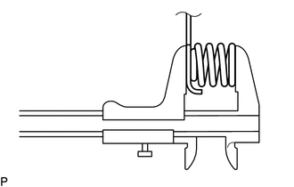
INSPECT 2ND BRAKE RETURN WITH RETAINER SPRING SUB-ASSEMBLY
-
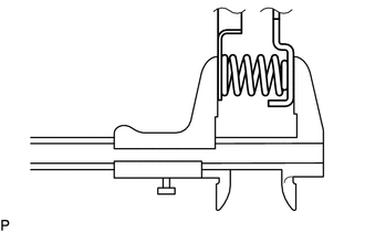
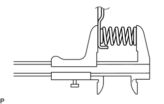
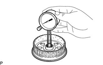
Using a vernier caliper, measure the free length of the 2nd brake return with retainer spring sub-assembly including the spring seat.
Standard Free Length 15.26 mm (0.601 in.) If the free length is less than the standard free length, replace the 2nd brake return with retainer spring sub-assembly.
-
-
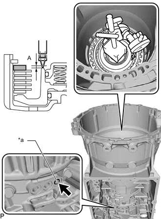
INSPECT PISTON STROKE OF NO. 1 BRAKE
-
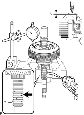
Inspect the piston stroke.
-
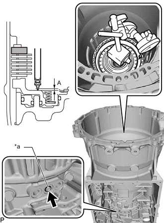
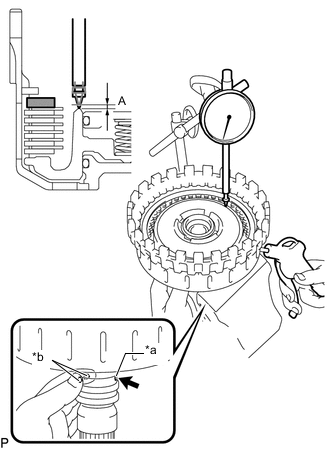
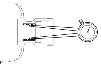
Using a dial indicator, measure the clearance (Dimension (A)) of the No. 1 brake at several points while applying compressed air (400 kPa (4.1 kgf/cm2, 58 psi)) to the oil hole as shown in the illustration, and calculate the average.
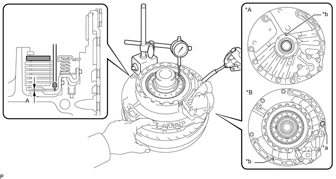
*A Front Side *B Rear Side *a Blow air into the oil hole *b Cover the oil hole 
No. 1 Brake Flange - - Standard Clearance 0.957 to 1.642 mm (0.0377 to 0.0646 in.) Tech Tips
The value is the average value obtained by measuring the dimension at 3 positions.
If the clearance is not as specified, check the installation condition, dimensions of each part and adjust the piston stroke.
-
-
Adjust the piston stroke.
-
Select the No. 1 brake flange and adjust the piston stroke value.
Standard Clearance 1.200 to 1.400 mm (0.0473 to 0.0551 in.) Tech Tips
There are 7 No. 1 brake flanges of different thicknesses.
No. 1 Brake Flange Thickness Part No. Mark Thickness 35676-11120 0 3.15 to 3.25 mm (0.125 to 0.127 in.) 35676-11130 1 3.25 to 3.35 mm (0.128 to 0.131 in.) 35676-11140 2 3.35 to 3.45 mm (0.132 to 0.135 in.) 35676-11150 3 3.45 to 3.55 mm (0.136 to 0.139 in.) 35676-11160 4 3.55 to 3.65 mm (0.140 to 0.143 in.) 35676-11170 5 3.65 to 3.75 mm (0.144 to 0.147 in.) 35676-11180 6 3.75 to 3.85 mm (0.148 to 0.151 in.)
-
-
-
INSPECT FRONT PLANETARY SUN GEAR SUB-ASSEMBLY
-
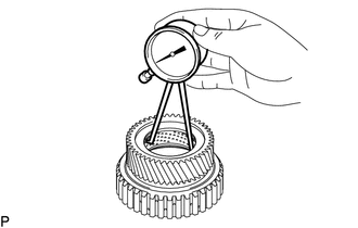
Using a caliper gauge, measure the inside diameter of the front planetary sun gear sub-assembly bushing.
Standard Inside Diameter 56.02 to 56.04 mm (2.2056 to 2.2062 in.) If the inside diameter is not as specified, replace the front planetary sun gear sub-assembly.
-
-
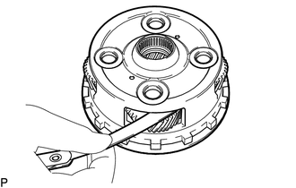
INSPECT FRONT PLANETARY GEAR ASSEMBLY
-
Using a feeler gauge, measure the clearance between the front planetary gear assembly and each pinion gear.
Standard Clearance 0.20 to 0.60 mm (0.00788 to 0.0236 in.) If the clearance is not as specified, replace the front planetary gear assembly.
-
-
INSPECT NO. 2 CLUTCH DISC
-
Check if the contact surfaces of the No. 2 clutch discs, No. 2 clutch plates and No. 2 clutch flange are worn or burnt.
If necessary, replace them.
Note
-
If the lining of any No. 2 clutch disc is peeled or discolored, or even if part of the printed number is damaged, replace all the No. 2 clutch discs.
-
Before installing new No. 2 clutch discs, soak them in ATF for at least 15 minutes.
-
-
-
INSPECT DIRECT CLUTCH RETURN SPRING SUB-ASSEMBLY (C-2 CLUTCH)
-
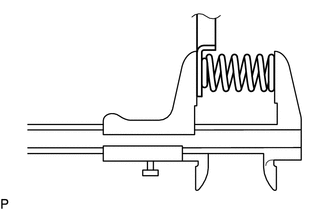
Using a vernier caliper, measure the free length of the direct clutch return spring sub-assembly (C-2 clutch) including the spring seat.
Standard Free Length 14.84 mm (0.584 in.) If the free length is less than the standard free length, replace the direct clutch return spring sub-assembly (C-2 clutch).
-
-
INSPECT PISTON STROKE OF NO. 2 CLUTCH
-
Inspect the piston stroke.
-
*a Blow air into the oil hole No. 2 Clutch Flange Using a dial indicator, measure the clearance (Dimension (A)) of the No. 2 clutch at several points while applying compressed air (400 kPa (4.1 kgf/cm2, 58 psi)) to the oil hole as shown in the illustration, and calculate the average.
Standard Clearance 0.9527 to 1.7673 mm (0.0376 to 0.0695 in.) Tech Tips
The value is the average value obtained by measuring the dimension at 3 positions.
If the clearance is not as specified, check the installation condition, dimensions of each part and adjust the piston stroke.
-
-
Adjust the piston stroke.
-
Select the No. 2 clutch flange and adjust the piston stroke value.
Standard Clearance 1.260 to 1.460 mm (0.0497 to 0.0574 in.) Tech Tips
There are 9 No. 2 clutch flanges of different thicknesses.
No. 2 Clutch Flange Thickness Part No. Mark Thickness 35635-11270 0 3.05 to 3.15 mm (0.121 to 0.124 in.) 35635-11280 1 3.15 to 3.25 mm (0.125 to 0.127 in.) 35635-11290 2 3.25 to 3.35 mm (0.128 to 0.131 in.) 35635-11300 3 3.35 to 3.45 mm (0.132 to 0.135 in.) 35635-11310 4 3.45 to 3.55 mm (0.136 to 0.139 in.) 35635-11320 5 3.55 to 3.65 mm (0.140 to 0.143 in.) 35635-11330 6 3.65 to 3.75 mm (0.144 to 0.147 in.) 35635-11340 7 3.75 to 3.85 mm (0.148 to 0.151 in.) 35635-11350 8 3.85 to 3.95 mm (0.152 to 0.155 in.)
-
-
-
INSPECT PISTON STROKE OF C-1 CLUTCH ASSEMBLY
Note
Do not disassemble the C-1 clutch assembly.
If disassembled, replace the C-1 clutch assembly with a new one.
-
Inspect the piston stroke.
-
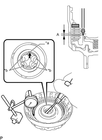
*a Blow air into the oil hole *b Cover the 4 oil holes No. 1 Clutch Flange Using a dial indicator, measure the clearance (Dimension (A)) of the No. 1 clutch at several points while applying compressed air (400 kPa (4.1 kgf/cm2, 58 psi)) to the oil hole as shown in the illustration, and calculate the average.
Standard Clearance 1.046 to 1.853 mm (0.0412 to 0.0729 in.) Tech Tips
The value is the average value obtained by measuring the dimension at 3 positions.
If the clearance is not as specified, replace the C-1 clutch assembly.
-
-
-
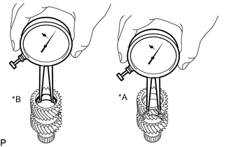
INSPECT C-1 CLUTCH ASSEMBLY
Note
Do not disassemble the C-1 clutch assembly.
If disassembled, replace the C-1 clutch assembly with a new one.
-
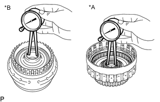
*A Front Side *B Rear Side Using a caliper gauge, measure the inside diameter of the C-1 clutch assembly bushing.
Standard Inside Diameter (Front Side) 47.021 to 47.046 mm (1.8513 to 1.8522 in.) Standard Inside Diameter (Rear Side) 42.012 to 42.037 mm (1.6541 to 1.6550 in.) If the inside diameter is not as specified, replace the C-1 clutch assembly.
-
-
INSPECT NO. 2 BRAKE DISC
-
Check if the contact surfaces of the No. 2 brake discs, No. 2 brake plates and No. 2 brake flange are worn or burnt.
If necessary, replace them.
Note
-
If the lining of any No. 2 brake disc is peeled or discolored, or even if part of the printed number is damaged, replace all the No. 2 brake discs.
-
Before installing new No. 2 brake discs, soak them in ATF for at least 15 minutes.
-
-
-
INSPECT 2ND BRAKE PISTON RETURN SPRING SUB-ASSEMBLY
-
Using a vernier caliper, measure the free length of the 2nd brake piston return spring sub-assembly including the spring seat.
Standard Free Length 15.66 mm (0.617 in.) If the free length is less than the standard free length, replace the 2nd brake piston return spring sub-assembly.
-
-
INSPECT PISTON STROKE OF NO. 2 BRAKE
-
Inspect the piston stroke.
-
*a Blow air into the oil hole No. 2 Brake Flange Using a dial indicator, measure the clearance (Dimension (A)) of the No. 2 brake at several points while applying compressed air (200 kPa (2.0 kgf/cm2, 29 psi)) to the oil hole as shown in the illustration, and calculate the average.
Standard Clearance 0.886 to 1.714 mm (0.0349 to 0.0674 in.) Tech Tips
The value is the average value obtained by measuring the dimension at 3 positions.
If the clearance is not as specified, check the installation condition, dimensions of each part and adjust the piston stroke.
-
-
Adjust the piston stroke.
-
Select the No. 2 brake flange and adjust the piston stroke value.
Standard Clearance 1.08 to 1.28 mm (0.0426 to 0.0503 in.) Tech Tips
There are 9 No. 2 brake flanges of different thicknesses.
No. 2 Brake Flange Thickness Part No. Mark Thickness 35678-11100 0 5.95 to 6.05 mm (0.235 to 0.238 in.) 35678-11110 1 6.05 to 6.15 mm (0.239 to 0.242 in.) 35678-11120 2 6.15 to 6.25 mm (0.243 to 0.246 in.) 35678-11130 3 6.25 to 6.35 mm (0.247 to 0.250 in.) 35678-11140 4 6.35 to 6.45 mm (0.251 to 0.253 in.) 35678-11150 5 6.45 to 6.55 mm (0.254 to 0.257 in.) 35678-11160 6 6.55 to 6.65 mm (0.258 to 0.261 in.) 35678-11170 7 6.65 to 6.75 mm (0.262 to 0.265 in.) 35678-11180 8 6.75 to 6.85 mm (0.266 to 0.269 in.)
-
-
-
INSPECT NO. 3 CLUTCH DISC
-
Check if the contact surfaces of the No. 3 clutch discs, No. 3 clutch plates and clutch flange are worn or burnt.
If necessary, replace them.
Note
-
If the lining of any No. 3 clutch disc is peeled or discolored, or even if part of a groove is damaged, replace all of the No. 3 clutch discs.
-
Before installing new No. 3 clutch discs, soak them in ATF for at least 15 minutes.
-
-
-
INSPECT DIRECT CLUTCH RETURN SPRING SUB-ASSEMBLY (C-3 CLUTCH)
-
Using a vernier caliper, measure the free length of the direct clutch return spring sub-assembly (C-3 clutch) including the spring seat.
Standard Free Length 17.56 mm (0.691 in.) If the free length is less than the standard free length, replace the direct clutch return spring sub-assembly (C-3 clutch).
-
-
INSPECT PISTON STROKE OF NO. 3 CLUTCH
-
Inspect the piston stroke.
-
*a Blow air into the oil hole Clutch Flange Using a dial indicator, measure the clearance (Dimension (A)) of the No. 3 clutch at several points while applying compressed air (400 kPa (4.1 kgf/cm2, 58 psi)) to the oil hole as shown in the illustration, and calculate the average.
Standard Clearance 0.671 to 1.529 mm (0.0265 to 0.0601 in.) Tech Tips
The value is the average value obtained by measuring the dimension at 3 positions.
If the clearance is not as specified, check the installation condition, dimensions of each part and adjust the piston stroke.
-
-
Adjust the piston stroke.
-
Select the clutch flange and adjust the piston stroke value.
Standard Clearance 1.000 to 1.200 mm (0.0394 to 0.0472 in.) Tech Tips
There are 9 clutch flanges of different thicknesses.
Clutch Flange Thickness Part No. Mark Thickness 35635-11380 0 3.05 to 3.15 mm (0.121 to 0.124 in.) 35635-11390 1 3.15 to 3.25 mm (0.125 to 0.127 in.) 35635-11400 2 3.25 to 3.35 mm (0.128 to 0.131 in.) 35635-11410 3 3.35 to 3.45 mm (0.132 to 0.135 in.) 35635-11420 4 3.45 to 3.55 mm (0.136 to 0.139 in.) 35635-11430 5 3.55 to 3.65 mm (0.140 to 0.143 in.) 35635-11440 6 3.65 to 3.75 mm (0.144 to 0.147 in.) 35635-11450 7 3.75 to 3.85 mm (0.148 to 0.151 in.) 35635-11460 8 3.85 to 3.95 mm (0.152 to 0.155 in.)
-
-
-
INSPECT CENTER SUPPORT SUB-ASSEMBLY
-
Using a caliper gauge, measure the inside diameter of the center support sub-assembly bushing.
Standard Inside Diameter 64.720 to 64.745 mm (2.5481 to 2.5490 in.) If the inside diameter is not as specified, replace the center support sub-assembly.
-
-
INSPECT CENTER PLANETARY GEAR ASSEMBLY
-
Using a feeler gauge, measure the clearance between the center planetary gear assembly and each pinion gear.
Standard Clearance 0.20 to 0.60 mm (0.00788 to 0.0236 in.) If the clearance is not as specified, replace the center planetary gear assembly.
-
-
INSPECT PLANETARY SUN GEAR SUB-ASSEMBLY
-
*A Front Side *B Rear Side Using a caliper gauge, measure the inside diameter of the planetary sun gear sub-assembly bushing.
Standard Inside Diameter (Front Side and Rear Side) 28.000 to 28.021 mm (1.1024 to 1.1031 in.) If the inside diameter is not as specified, replace the planetary sun gear sub-assembly.
-
-
INSPECT REAR PLANETARY GEAR ASSEMBLY
-
Using a feeler gauge, measure the clearance between the rear planetary gear assembly and each pinion gear.
Standard Clearance 0.20 to 0.60 mm (0.00788 to 0.0236 in.) If the clearance is not as specified, replace the rear planetary gear assembly.
-
-
INSPECT REAR PLANETARY RING GEAR FLANGE SUB-ASSEMBLY
-
Using a caliper gauge, measure the inside diameter of the rear planetary ring gear flange sub-assembly bushing.
Standard Inside Diameter 22.245 to 22.270 mm (0.8758 to 0.8767 in.) If the inside diameter is not as specified, replace the rear planetary ring gear flange sub-assembly.
-
-
INSPECT NO. 4 CLUTCH DISC
-
Check if the contact surfaces of the No. 4 clutch discs, No. 4 clutch plates and clutch flange are worn or burnt.
If necessary, replace them.
Note
-
If the lining of any No. 4 clutch disc is peeled or discolored, or even if part of a groove is damaged, replace all of the No. 4 clutch discs.
-
Before installing new No. 4 clutch discs, soak them in ATF for at least 15 minutes.
-
-
-
INSPECT DIRECT CLUTCH RETURN SPRING SUB-ASSEMBLY (C-4 CLUTCH)
-

Using a vernier caliper, measure the free length of the direct clutch return spring sub-assembly (C-4 clutch) including the spring seat.
Standard Free Length 19.02 mm (0.749 in.) If the free length is less than the standard free length, replace the direct clutch return spring sub-assembly (C-4 clutch).
-
-
INSPECT PISTON STROKE OF NO. 4 CLUTCH
-
Inspect the piston stroke.
-
*a Blow air into the oil hole *b Cover the 2 oil holes Clutch Flange Using a dial indicator, measure the clearance (Dimension (A)) of the No. 4 clutch at several points while applying compressed air (400 kPa (4.1 kgf/cm2, 58 psi)) to the oil hole as shown in the illustration, and calculate the average.
Standard Clearance 0.50 to 0.90 mm (0.0197 to 0.0354 in.) Tech Tips
The value is the average value obtained by measuring the dimension at 3 positions.
If the clearance is not as specified, check the installation condition, dimensions of each part and adjust the piston stroke.
-
-
Adjust the piston stroke.
-
Select the clutch flange and adjust the piston stroke value.
Standard Clearance 1.080 to 1.280 mm (0.0426 to 0.0503 in.) Tech Tips
There are 9 clutch flanges of different thicknesses.
Clutch Flange Thickness Part No. Thickness 35635-11470 3.85 to 3.95 mm (0.152 to 0.155 in.) 35635-11480 3.95 to 4.05 mm (0.156 to 0.159 in.) 35635-11490 4.05 to 4.15 mm (0.160 to 0.163 in.) 35635-11500 4.15 to 4.25 mm (0.164 to 0.167 in.) 35635-11510 4.25 to 4.35 mm (0.168 to 0.171 in.) 35635-11520 4.35 to 4.45 mm (0.172 to 0.175 in.) 35635-11530 4.45 to 4.55 mm (0.176 to 0.179 in.) 35635-11540 4.55 to 4.65 mm (0.180 to 0.183 in.) 35635-11550 4.65 to 4.75 mm (0.184 to 0.187 in.)
-
-
-
INSPECT INDIVIDUAL PISTON OPERATION
-
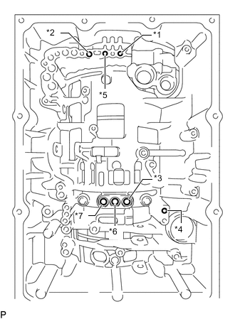
*1 No. 1 Clutch (C-1) *2 No. 2 Clutch (C-2) *3 No. 3 Clutch (C-3) *4 No. 4 Clutch (C-4) *5 No. 1 Brake (B-1) *6 No. 2 Brake (B-2 (In)) *7 No. 2 Brake (B-2 (Out)) Check the operating sound of each piston while applying compressed air to each oil hole shown in the illustration.
-
-
INSPECT AUTOMATIC TRANSMISSION CASE
-
Using a caliper gauge, measure the inside diameter of the automatic transmission case sleeve bushing.
Standard Free Length 43.870 to 43.955 mm (1.7272 to 1.7305 in.) If the inside diameter is not as specified, replace the automatic transmission case.
-