CENTER BODY PILLAR CUT AND JOIN REPLACEMENT SECTIONS
-
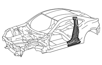
With the quarter panel removed.
- Weld work for 980 MPa ultra high strength steel
-
*1: When welding 2 panels together including 980 MPa ultra high strength steel.
Plug weld Plug diameter 10 mm (0.39 in.) Wire type AWS A5.18 ER70S-3 Shield gas Metal active gas
Follow the welding conditions below when welding ultra high strength steel to assure sufficient weld strength. (When repairing this model)
-
*2: When welding more than 3 panels together including 980 MPa ultra high strength steel. (When plug welding a third panel to 2 panels which are welded under the conditions described above.)
Plug weld Plug diameter Same as the standard method (See the introduction) Wire type AWS A5.18 ER70S-3 Shield gas Metal active gas
-
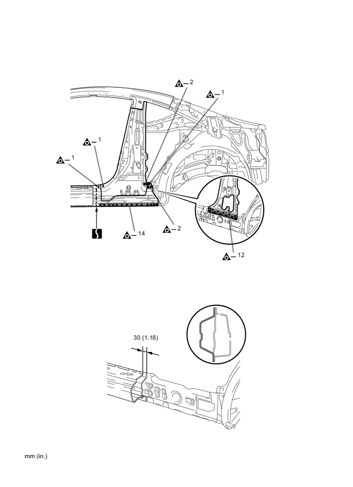
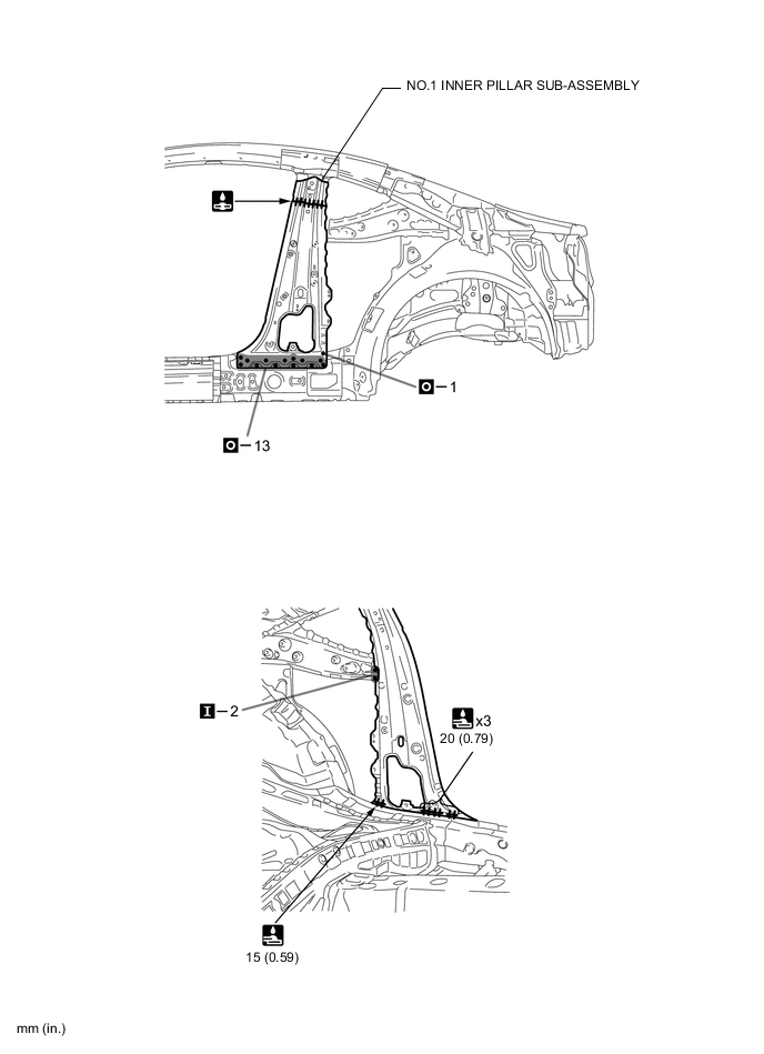
REMOVAL
Symbol meaning 
Remove Weld Points 
Remove Weld Points 
Cut with Disc Sander etc. 
Cut and Join Location
-
Do not butt weld or heat repair because the heat decreases the strength of areas where ultra high strength steel is used. (See the introduction)
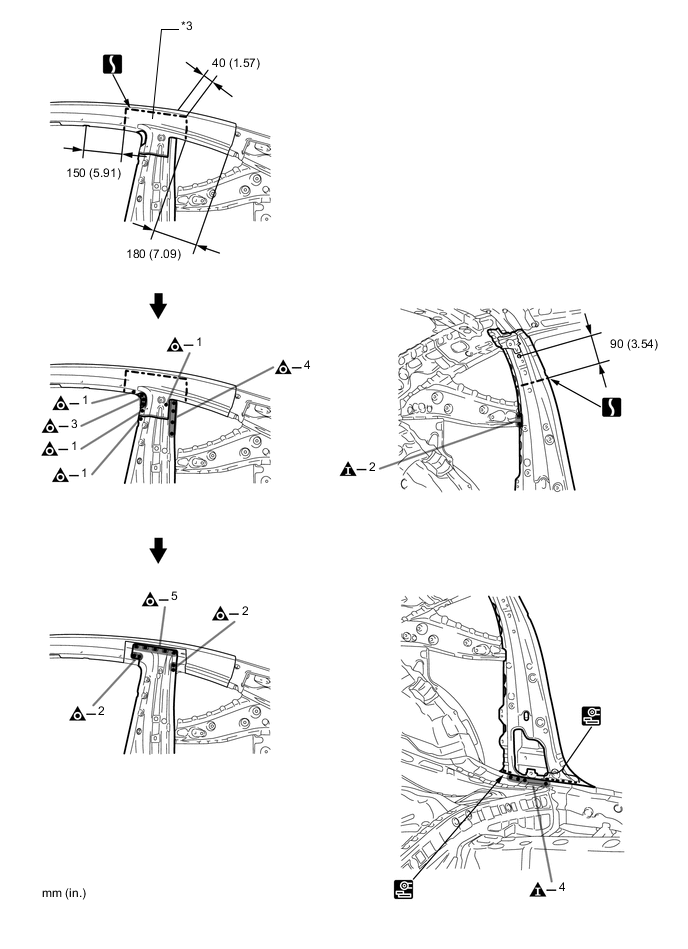
-
*3 is reused.
REMOVAL POINT
-
-
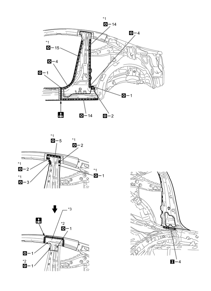
INSTALLATION
Symbol meaning 
Plug Weld 
Plug Weld Cut and Join Location 
Fillet Weld 
Butt Weld
-
Inspect the fitting of the related parts around the new parts before welding. This affects the appearance of the finish.
-
Temporarily install the new parts and measure each part of the new parts in accordance with the body dimension diagram. (See the body dimensions)
-
If the entire supply part is not needed, remove the part of the supply part that is needed.
-
Follow the welding conditions when welding *1 and *2 to assure sufficient weld strength. (See the introduction)
-
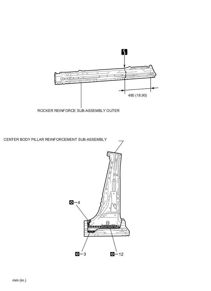
Before temporarily installing the new parts, weld the center body pillar reinforcement sub-assembly and rocker reinforce sub-assembly outer with the standard number of welding points.
-
After welding the No.1 inner pillar sub-assembly the vehicle side, install the center body pillar reinforcement sub-assembly and rocker reinforce sub-assembly outer.
-
After welding the No.1 inner pillar sub-assembly, center body pillar reinforcement sub-assembly and rocker reinforce sub-assembly outer the vehicle side, install the *3.
-
After welding, apply body sealer to the corresponding parts. (See the painting / coating)
-
After applying the top coat, apply anti-rust agent to the internal panel portion of the closed section structural weld points.
INSTALLATION POINT
-