CXPI COMMUNICATION SYSTEM, Diagnostic DTC:B2362
| DTC Code | DTC Name |
|---|---|
| B2362 | Lost Communication with overhead Module |
DESCRIPTION
This DTC is stored when CXPI communication between the map light sub-assembly and main body ECU (multiplex network body ECU) stops for 10 seconds or more.
| DTC No. | Detection Item | DTC Detection Condition | Trouble Area |
|---|---|---|---|
| B2362 | Lost Communication with overhead Module | No communication between map light sub-assembly and main body ECU (multiplex network body ECU) for 10 seconds or more |
|
WIRING DIAGRAM
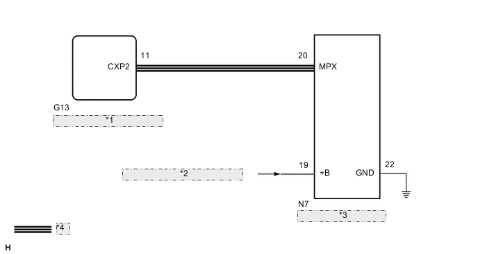
| *1 | Main Body ECU (Multiplex Network Body ECU) |
| *2 | from Engine Stop and Start ECU |
| *3 | Map Light Sub-assembly |
| *4 | CXPI Communication Line |
CAUTION / NOTICE / HINT
Note
-
When using the GTS with the engine switch off to troubleshoot:
Connect the GTS to the vehicle, and turn a courtesy switch on and off at 1.5 second intervals until communication between the GTS and vehicle begins.
-
Recognition code registration is necessary when replacing the main body ECU (multiplex network body ECU).
-
If the main body ECU (multiplex network body ECU) is replaced, refer to the Service Bulletin.
PROCEDURE
-
CLEAR DTC
-
Clear the DTCs.
Body Electrical > Main Body > Clear DTCsResult Proceed to NEXT
NEXT 
-
-
CHECK FOR DTC
-
Check for DTCs.
Body Electrical > Main Body > Trouble CodesResult Proceed to DTC B2362 is output DTC B2362 is not output
DTC B2362 is not output 
USE SIMULATION METHOD TO CHECK Click here
DTC B2362 is output
-
-
CHECK HARNESS AND CONNECTOR (MAP LIGHT SUB-ASSEMBLY - BATTERY AND BODY GROUND)
-
Disconnect the N7 map light sub-assembly connector.
-
Measure the voltage according to the value(s) in the table below.
Standard Voltage Tester Connection Condition Specified Condition N7-19 (+B) - Body ground Always 10.5 to 16 V -
Measure the resistance according to the value(s) in the table below.
Standard Resistance Tester Connection Condition Specified Condition N7-22 (GND) - Body ground Always Below 1 Ω Result Proceed to OK NG
NG
REPAIR OR REPLACE HARNESS OR CONNECTOR
OK
-
-
CHECK HARNESS AND CONNECTOR (MAP LIGHT SUB-ASSEMBLY - MAIN BODY ECU [MULTIPLEX NETWORK BODY ECU])
-
Disconnect the G13 main body ECU (multiplex network body ECU) connector.
-
Disconnect the N7 map light sub-assembly connector.
-
Measure the resistance according to the value(s) in the table below.
Standard Resistance Tester Connection Condition Specified Condition G13-11 (CXP2) - N7-20 (MPX) Always Below 1 Ω G13-11 (CXP2) - Body ground Always 10 kΩ or higher Result Proceed to OK NG
NG
REPAIR OR REPLACE HARNESS OR CONNECTOR
OK
-
-
REPLACE MAP LIGHT SUB-ASSEMBLY
-
Temporarily replace the map light sub-assembly with a new or normally functioning one.
Result Proceed to NEXT
NEXT
-
-
CLEAR DTC
-
Clear the DTCs.
Body Electrical > Main Body > Clear DTCsResult Proceed to NEXT
NEXT
-
-
CHECK FOR DTC
-
Check for DTCs.
Body Electrical > Main Body > Trouble CodesResult Proceed to DTC B2362 is output DTC B2362 is not output
DTC B2362 is output
REPLACE MAIN BODY ECU (MULTIPLEX NETWORK BODY ECU) Click here
DTC B2362 is not output
END (MAP LIGHT SUB-ASSEMBLY IS DEFECTIVE)
-