AIR CONDITIONING SYSTEM (for Automatic Air Conditioning System) TERMINALS OF ECU
-
CHECK AIR CONDITIONING AMPLIFIER ASSEMBLY

-
Disconnect the A44 air conditioning amplifier assembly connector.
-
Measure the voltage and resistance according to the value(s) in the table below.
Terminal No. (Symbol) Wiring Color Terminal Description Condition Specified Condition A44-1 (GND) - Body ground L - Body ground Ground Always Below 1 Ω A44-5 (+B1) - A44-1 (GND) L-Y - L Battery power source Always 11 to 14 V A44-6 (IG+) - A44-1 (GND) R-L - L Ignition power source Ignition switch off Below 1 V Ignition switch ON 11 to 14 V A44-13 (MGC) - Body ground B - Body ground Magnet clutch signal Ignition switch ON 11 to 14 V Ignition switch off Below 1 V A44-14 (HR) - Body ground L-W - Body ground HTR relay signal Ignition switch ON 11 to 14 V Ignition switch off Below 1 V
-
If the result is not as specified, there may be a malfunction on the wire harness side.
-
-
Reconnect the A44 air conditioning amplifier assembly connector.
-
Measure the voltage and resistance according to the value(s) in the table below.
Terminal No. (Symbol) Wiring Color Terminal Description Condition Specified Condition A44-2 (BLW) - Body ground L-B - Body ground Blower motor speed control voltage
-
Ignition switch ON
-
Blower switch on (LO level)
Pulse generation
(See waveform 1)
A44-3 (AOF) - A44-1 (GND) Y-B - L Mode damper servo operation voltage
-
Ignition switch ON
-
Mode switch DEF
Below 1 V
-
Ignition switch ON
-
Mode switch FACE
11 to 14 V A44-4 (AOD) - A44-1 (GND) R-B - L Mode damper servo operation voltage
-
Ignition switch ON
-
Mode switch FACE
Below 1 V
-
Ignition switch ON
-
Mode switch DEF
11 to 14 V A44-7 (ACT) - A44-1 (GND) R-L - L Magnet clutch on permit input signal
-
Engine idling
-
Blower switch on (LO level)
-
A/C switch off
Below 1 V
-
Engine idling
-
Blower switch on (LO level)
-
A/C switch on
11 to 14 V A44-8 (TW) - A44-1 (GND) P - L Engine coolant temperature sensor signal Ignition switch ON Pulse generation A44-9 (SPD) - Body ground V-W - Body ground Vehicle speed signal Driving at approximately 20 km/h (12 mph) Pulse generation
(See waveform 2)
A44-13 (MGC) - Body ground B - Body ground Magnet clutch signal
-
Engine idling
-
A/C switch on
Below 1 V
-
Engine idling
-
A/C switch off
11 to 14 V A44-17 (AMH) - A44-1 (GND) L - L Air mix damper servo operation signal
-
Ignition switch ON
-
Temperature switch MAX HOT
11 to 14 V
-
Ignition switch ON
-
Temperature switch MAX COLD
Below 1 V A44-18 (TAMO) - A44-1 (GND) P - L Ambient temperature signal Ignition switch ON Pulse generation A44-19 (AMC) - A44-1 (GND) R-W - L Air mix damper servo operation signal
-
Ignition switch ON
-
Temperature switch MAX HOT
Below 1 V
-
Ignition switch ON
-
Temperature switch MAX COLD
11 to 14 V A44-21 (AC1) - A44-1 (GND) Y - L Idle-up request signal
-
Engine idling
-
Blower switch on (LO level)
-
A/C switch off or on (magnet clutch off)
11 to 14 V
-
Engine idling
-
Blower switch on (LO level)
-
A/C switch on (magnet clutch on)
Below 1 V A44-22 (AIR) - A44-1 (GND) L-W - L Recirculation damper servo operation voltage
-
Ignition switch ON
-
Fresh switch on
Below 1 V
-
Ignition switch ON
-
Recirculation switch on
11 to 14 V A44-23 (AIF) - A44-1 (GND) G-Y - L Recirculation damper servo operation voltage
-
Ignition switch ON
-
Recirculation switch on
Below 1 V
-
Ignition switch ON
-
Fresh switch on
11 to 14 V A46-1 (TE) - A46-14 (SG-4) G - P No. 1 cooler thermistor signal
-
Ignition switch ON
-
Evaporator temperature 0°C (32°F)
2 to 2.4 V
-
Ignition switch ON
-
Evaporator temperature 15°C (59°F)
1.4 to 1.8 V A46-2 (S5-3) - A44-1 (GND) W-R - L Power supply for solar sensor Ignition switch ON 4.5 to 5.5 V A46-5 (PSW) - A44-1 (GND) Y-B - L Air conditioner pressure sensor signal
-
Engine idling
-
Refrigerant pressure normal
Below 1 V
-
Engine idling
-
Refrigerant pressure less than 0.196 MPa (2.0 kgf/cm2, 28 psi) or more than 3.14 MPa (32.0 kgf/cm2, 455 psi)
11 to 14 V A46-7 (TS) - A46-2 (S5-3) L-W - W-R Solar sensor signal
-
Ignition switch ON
-
Solar sensor subjected to electric light
-
Vehicle indoors
0.8 to 4.3 V
-
Ignition switch ON
-
Solar sensor covered with cloth
-
Vehicle indoors
Below 0.8 V A46-9 (VER) - Body ground*1 R - Body ground Steering wheel location information signal Always Below 1 Ω A46-11 (SG-2) - Body ground L-Y - Body ground Ground for pulse position sensor (Mode damper servo) Always Below 1 Ω A46-13 (SG-3) - Body ground BR-Y - Body ground Ground for cooler thermistor Always Below 1 Ω A46-14 (SG-4) - Body ground P - Body ground Ground for No. 1 cooler thermistor Always Below 1 Ω A46-16 (PIB) - A46-21 (SG-7) R-L - LG-R Input signal for pulse position sensor (recirculation damper servo)
-
Ignition switch ON
-
Air inlet control recirculation to fresh or vice versa
Pulse generation A46-17 (PIA) - A46-21 (SG-7) P-B - LG-R Input signal for pulse position sensor (recirculation damper servo)
-
Ignition switch ON
-
Air inlet control recirculation to fresh or vice versa
Pulse generation A46-18 (TR) - A46-13 (SG-3) GR - BR-Y Cooler thermistor signal
-
Ignition switch ON
-
Cabin temperature 25°C (77°F)
1.8 to 2.2 V
-
Ignition switch ON
-
Cabin temperature 40°C (104°F)
1.2 to 1.6 V A46-20 (SG-1) - Body ground BR-Y - Body ground Ground for pulse position sensor (air mix damper servo) Always Below 1 V A46-21 (SG-7) - Body ground LG-R - Body ground Ground for pulse position sensor (recirculation damper servo) Always Below 1 Ω A46-23 (PMB) - A46-20 (SG-1) W-L - BR-Y Input signal for pulse position sensor (air mix damper servo)
-
Ignition switch ON
-
Temperature switch MAX HOT to MAX COLD
Pulse generation A46-24 (PMA) - A46-20 (SG-1) W-R - BR-Y Input signal for pulse position sensor (air mix damper servo)
-
Ignition switch ON
-
Temperature switch MAX COLD to MAX HOT
Pulse generation A46-25 (POB) - A46-11(SG-2) LG - L-Y Input signal for pulse position sensor (mode damper servo)
-
Ignition switch ON
-
Mode control FACE to DEF or vice versa
Pulse generation A46-26 (POA) - A46-11 (SG-2) L-O - L-Y Input signal for pulse position sensor (mode damper servo)
-
Ignition switch ON
-
Mode control FACE to DEF or vice versa
Pulse generation A43-3 (PTCR) - A44-1 (GND)* L-W - L Idle-up request signal for PTC heater
-
Ignition switch ON
-
Power heater switch off
11 to 14 V
-
Ignition switch ON
-
Power heater switch on
Below 1 V A44-11 (IGN) - A44-1 (GND)*2 B-W - L Engine speed signal Engine idling Pulse generation A43-7 (TAIL) - A44-1 (GND)*2 G - L Light control switch signal Light control switch OFF Below 1 V A43-6 (ALT) - A44-1 (GND)*2 G - L Generator input signal Engine idling Pulse generation A43-1 (PTC1) - A44-1 (GND)*2 R-W - L No. 1 PTC heater relay signal
-
Engine idling
-
Temperature switch MAX COLD to MAX HOT
-
Coolant temperature 65°C (149°F) or less
-
Ambient temperature 10°C (50°F) or less
-
Headlight dimmer switch not in head position
-
Generator is operating
-
Blower switch on (Lo level)
-
Heater switch assembly on
11 to 14 V
-
Engine idling
-
Temperature switch MAX COLD to MAX HOT
-
Coolant temperature 65°C (149°F) or less
-
Ambient temperature 10°C (50°F) or less
-
Headlight dimmer switch not in head position
-
Generator is operating
-
Blower switch on (Lo level)
-
Heater switch assembly off
Below 1 V A43-2 (PTC2) - A44-1 (GND)*2 GR - L No. 2 PTC heater relay signal
-
Engine idling
-
Temperature switch MAX COLD to MAX HOT
-
Coolant temperature 65°C (149°F) or less
-
Ambient temperature 10°C (50°F) or less
-
Headlight dimmer switch not in head position
-
Generator is operating
-
Blower switch on (Lo level)
-
Heater switch assembly on
11 to 14 V
-
Engine idling
-
Temperature switch MAX COLD to MAX HOT
-
Coolant temperature 65°C (149°F) or less
-
Ambient temperature 10°C (50°F) or less
-
Headlight dimmer switch not in head position
-
Generator is operating
-
Blower switch on (Lo level)
-
Heater switch assembly off
Below 1 V A43-8 (HEAT) - A44-1 (GND)*2 L-O - L Power heater switch input signal
-
Ignition switch ON
-
Power heater switch on
Below 1 V
-
Ignition switch ON
-
Power heater switch off
11 to 14 V A43-5 (SWIN) - A44-1 (GND)*2 P - L Power heater switch indicator light signal
-
Ignition switch ON
-
Power heater switch on
Below 1 V
-
Ignition switch ON
-
Power heater switch off
11 to 14 V
-
*1: for LHD
-
*2: w/ PTC Heater
-
If the result is not as specified, the air conditioning amplifier assembly may have a malfunction.
-
-
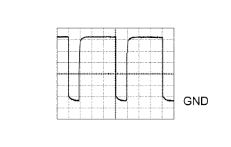
Using an oscilloscope, check waveform 1.
Blower motor control signal Item Content Terminal No. (Symbol) A44-2 (BLW) - Body ground Tool Setting 1 V/DIV., 50 μsec./DIV. Condition Ignition switch ON, Blower switch on (LO level) Tech Tips
When the blower level is increased, the duty ratio changes accordingly.
-
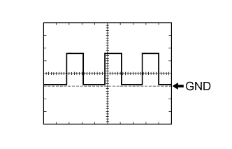
Using an oscilloscope, check waveform 2.
Vehicle speed signal Item Content Terminal No. (Symbol) A44-9 (SPD) - Body ground Tool Setting 5 V/DIV., 20 ms./DIV. Condition Driving at approximately 20 km/h (12 mph) Tech Tips
As the vehicle speed increases, the wavelength becomes shorter.
-
-
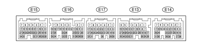
CHECK ECM (for 1GR-FE)
-
Measure the voltage according to the value(s) in the table below.
Terminal No. (Symbol) Wiring Color Terminal Description Condition Specified Condition E13-14 (THWO) - E17-1 (E1) P - BR Engine coolant temperature output signal Engine idling Pulse generation E13-24 (AC1) - E17-1 (E1) Y - BR Idle-up request signal
-
Engine idling
-
Blower switch on (LO level)
-
A/C switch on (magnet clutch on)
Below 1 V
-
Engine idling
-
Blower switch on (LO level)
-
A/C switch off or on (magnet clutch off)
11 to 14 V E13-25 (ACT) - E17-1 (E1) R-L - BR Magnet clutch on permit output signal
-
Engine idling
-
Blower switch on (LO level)
-
A/C switch off
Below 1 V
-
Engine idling
-
Blower switch on (LO level)
-
A/C switch on
11 to 14 V E15-21 (THW) - E15-28 (E2) B - BR Engine coolant temperature sensor signal
-
Engine idling
-
Engine coolant temperature 20°C (68°F)
0.2 to 1.0 V If the result is not as specified, the ECM may have a malfunction.
-
-
-
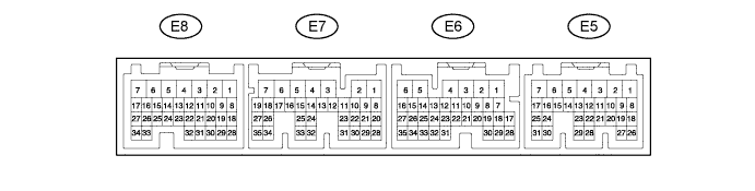
CHECK ECM (for 1KD-FTV, 2KD-FTV)
-
Measure the voltage according to the value(s) in the table below.
Terminal No. (Symbol) Wiring Color Terminal Description Condition Specified Condition E5-2 (THWO) - E7-7 (E1) P - BR Engine coolant temperature output signal Engine idling Pulse generation E6-18 (AC1) - E7-7 (E1) Y - BR Idle-up request signal
-
Engine idling
-
Blower switch on (LO level)
-
A/C switch on (magnet clutch on)
Below 1 V
-
Engine idling
-
Blower switch on (LO level)
-
A/C switch off or on (magnet clutch off)
11 to 14 V E6-19 (ACT) - E7-7 (E1) R-L - BR Magnet clutch on permit output signal
-
Engine idling
-
Blower switch on (LO level)
-
A/C switch off
Below 1 V
-
Engine idling
-
Blower switch on (LO level)
-
A/C switch on
11 to 14 V E8-19 (THW) - E8-28 (E2) R-L - BR Engine coolant temperature sensor signal
-
Engine idling
-
Engine coolant temperature 20°C (68°F)
0.2 to 1.0 V If the result is not as specified, the ECM may have a malfunction.
-
-
-
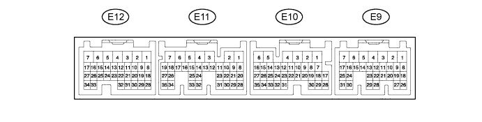
CHECK ECM (for 2TR-FE)
-
Measure the voltage according to the value(s) in the table below.
Terminal No. (Symbol) Wiring Color Terminal Description Condition Specified Condition E10-14 (THWO) - E12-3 (E1) P - BR Engine coolant temperature output signal Engine idling Pulse generation E10-24 (AC1) - E12-3 (E1) Y - BR Idle-up request signal
-
Engine idling
-
Blower switch on (LO level)
-
A/C switch on (magnet clutch on)
Below 1 V
-
Engine idling
-
Blower switch on (LO level)
-
A/C switch off or on (magnet clutch off)
11 to 14 V E10-25 (ACT) - E12-3 (E1) R-L - BR Magnet clutch on permit output signal
-
Engine idling
-
Blower switch on (LO level)
-
A/C switch off
Below 1 V
-
Engine idling
-
Blower switch on (LO level)
-
A/C switch on
11 to 14 V E12-32 (THW) - E12-28 (E2) B - BR Engine coolant temperature sensor signal
-
Engine idling
-
Engine coolant temperature 20°C (68°F)
0.2 to 1.0 V If the result is not as specified, the ECM may have a malfunction.
-
-
-
CHECK ACCESSORY METER ASSEMBLY

-
Measure the voltage according to the value(s) in the table below.
Terminal No. (Symbol) Wiring Color Terminal Description Condition Specified Condition A27-3 (TH+) - A27-2 (SG) W-G - BR-Y*1
L - BR*2
W-G - BR-Y*3
Ambient temperature sensor signal
-
Ignition switch ON
-
Ambient temperature 20 to 30°C (68 to 86°F)
1 to 1.6 V Ambient temperature sensor signal
-
Ignition switch ON
-
Ambient temperature 30 to 50°C (86 to 122°F)
0.6 to 1 V A27-9 (DATA) - A27-1 (GND1) P - LG Ambient temperature sensor signal Ignition switch ON Pulse generation
-
*1: for Europe, w/ Light Control Rheostat
-
*2: for Europe, w/o Light Control Rheostat
-
*3: except Europe
-
If the result is not as specified, the accessory meter assembly may have a malfunction.
-
-
-
CHECK COMBINATION METER ASSEMBLY

-
Measure the voltage according to the value(s) in the table below.
Terminal No. (Symbol) Wiring Color Terminal Description Condition Specified Condition C8-6 - C8-22 V-R - Y Vehicle speed signal Driving at approximately 20 km/h (12 mph) Pulse generation
(See waveform)
-
If the result is not as specified, the combination meter assembly may have a malfunction.
-
-
Using an oscilloscope, check waveform 1.
Vehicle speed signal Item Content Terminal No. (Symbol) C8-6 - C8-22 Tool Setting 5 V/DIV., 20 ms./DIV. Condition Driving at approximately 20 km/h (12 mph) Tech Tips
When the blower level is increased, the duty ratio changes accordingly.
-