MAIN BODY ECU REMOVAL
PROCEDURE
DISCONNECT CABLE FROM NEGATIVE BATTERY TERMINAL
Note:After turning the engine switch off, waiting time may be required before disconnecting the cable from the battery terminal. Therefore, make sure to read the disconnecting the cable from the battery terminal notice before proceeding with work (Click here).
When disconnecting the cable, some systems need to be initialized after the cable is reconnected (Click here).
REMOVE DOOR SCUFF PLATE ASSEMBLY LH
REMOVE COWL SIDE TRIM BOARD LH
REMOVE NO. 1 INSTRUMENT PANEL UNDER COVER SUB-ASSEMBLY
REMOVE FRONT NO. 1 CONSOLE BOX INSERT
REMOVE INSTRUMENT PANEL FINISH PANEL END LH
REMOVE INSTRUMENT SIDE PANEL LH
REMOVE NO. 2 SWITCH HOLE BASE
REMOVE NO. 1 INSTRUMENT PANEL FINISH CUSHION
REMOVE LOWER INSTRUMENT PANEL FINISH PANEL ASSEMBLY
REMOVE NO. 1 INSTRUMENT PANEL REGISTER ASSEMBLY
REMOVE LOWER INSTRUMENT PANEL FINISH PANEL SUB-ASSEMBLY
REMOVE LOWER NO. 1 INSTRUMENT PANEL AIRBAG ASSEMBLY
REMOVE DRIVER SIDE JUNCTION BLOCK ASSEMBLY
-
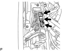
Disconnect the 3 connectors.
-
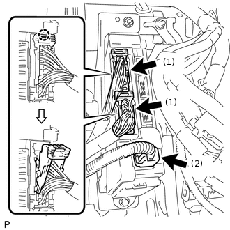
Detach the 2 claws and disconnect the 2 connectors labeled (1) as shown in the illustration.
Disconnect the connector labeled (2).
-
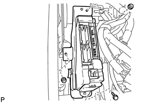
Remove the bolt and 2 nuts and disconnect the driver side junction block assembly.
-
Detach the claw and disconnect the connector as shown in the illustration.
-
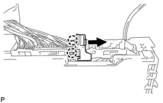
Detach the 2 claws and release the connector's lock as shown in the illustration.
-
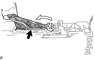
Detach the claw and disconnect the connector as shown in the illustration.
Remove the driver side junction block assembly.
-
REMOVE MULTIPLEX NETWORK BODY ECU
-
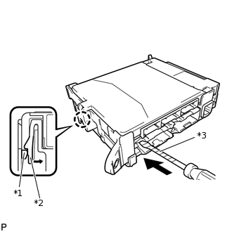
*1
Multiplex Network Body ECU
*2
Driver Side Junction Block
*3
Protective Tape
Press the claw of the junction block as shown in the illustration to release the lock.
With the junction block lock released, insert a screwdriver with its tip wrapped with protective tape horizontally between the multiplex network body ECU and junction block.
Note:Use a screwdriver with a radius of between 5.0 mm (0.197 in.) and 6.3 mm (0.248 in.) and a length of approximately 90 mm (3.54 in.).
-
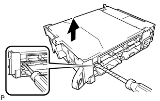
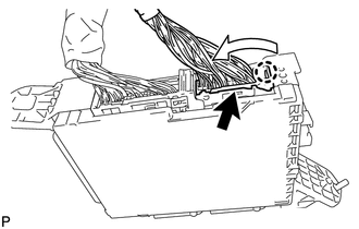
Using the screwdriver, carefully raise the multiplex network body ECU until the connector becomes disengaged.
Note:Do not twist the screwdriver to raise the multiplex network body ECU.
-
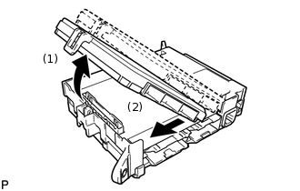
Raise the multiplex network body ECU as shown by arrow (1), and then pull it out as shown by arrow (2) in the illustration.
Note:Do not touch the ECU connector.
-