SLIDING ROOF HOUSING(for Panoramic Moon Roof) INSTALLATION
PROCEDURE
-
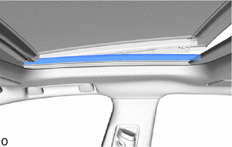
INSTALL SLIDING ROOF HOUSING ASSEMBLY
-
Pass a string under the No. 1 back window moulding as shown in the illustration.
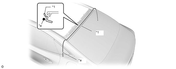
*1 No. 1 back window moulding - - *a String - - -
Attach the guide.
-
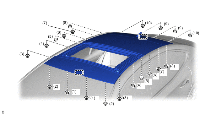
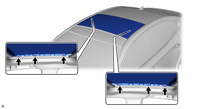
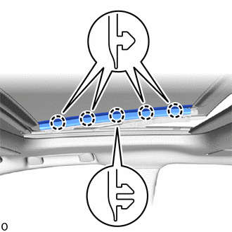
Temporarily install the sliding roof housing assembly with the 20 nuts.
Note
If the removed nut is the same shape as that shown in the illustration, replace it the supplied replacement part.

-
Tighten the 20 nuts to install the sliding roof housing assembly.
- Torque:
- 8.0 N*m { 82 kgf*cm, 71 in.*lbf }
Tech Tips
Tighten the nuts in the order shown in the illustration.
-
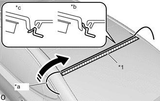
*1 No. 1 back window moulding *a String *b Correct *c Incorrect Apply soapy water to the No. 1 back window moulding.
-
Slowly pull out the string to install the No. 1 back window moulding to the correct position.
-
-
INSTALL REMOVABLE ROOF BRACKET REINFORCEMENT LH
-
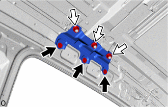

Bolt 
Nut Install the removable roof bracket reinforcement LH with the 3 bolts and 3 nuts.
- Torque:
- Bolt, Nut
- 8.0 N*m { 82 kgf*cm, 71 in.*lbf }
-
-
INSTALL REMOVABLE ROOF BRACKET REINFORCEMENT RH
Tech Tips
Use the same procedure as for the LH side.
-
INSTALL FRONT SLIDING ROOF HOUSING MOUNTING BRACKET LH
-
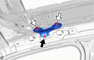
Bolt Nut Install the front sliding roof housing mounting bracket LH with the bolt and 2 nuts.
- Torque:
- Bolt, Nut
- 8.0 N*m { 82 kgf*cm, 71 in.*lbf }
Note
If the removed nut is the same shape as that shown in the illustration, replace it the supplied replacement part.
-
-
INSTALL FRONT SLIDING ROOF HOUSING MOUNTING BRACKET RH
Tech Tips
Use the same procedure as for the LH side.
-
INSTALL SLIDING ROOF GLASS SUB-ASSEMBLY
-
Using a T25 "TORX" socket wrench, temporarily install the sliding roof glass sub-assembly with the 6 screws.
-
Perform a level check.
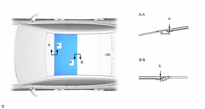
-
Check the difference in level of the sliding roof glass sub-assembly when the sliding roof glass sub-assembly is fully closed.
Tech Tips
"+" represents the condition that the glass is above the panel level. "-" represents the condition that the glass is below the panel level.
Area Measurement Area Measurement Front[a] 0 + 2.0 mm (0 + 0.0787 in.) Rear[b] 0 + 1.5 mm (0 + 0.0591 in.)
0 - 1.0 mm (0 - 0.0394 in.)
-
-
Perform a gap check.
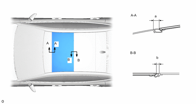
-
Check the gap between the sliding roof glass sub-assembly and sliding roof housing assembly.
Area Measurement Area Measurement Front[a] 17.3 to 19.3 mm (0.681 to 0.760 in.) Rear[b] 7.1 to 10.1 mm (0.280 to 0.398 in.)
-
-
After adjusting the sliding roof glass sub-assembly, using a T25 "TORX" socket wrench, tighten the 6 screws.
- Torque:
- 5.0 N*m { 51 kgf*cm, 44 in.*lbf }
-
-
CHECK FOR WATER LEAK
-
After adjusting the sliding roof glass sub-assembly, check for water leakage into the vehicle interior.
-
If there are any leaks, readjust the sliding roof glass sub-assembly.
-
-
INSTALL SLIDING ROOF SIDE GARNISH LH
-
Install the sliding roof side garnish LH.
Tech Tips
Make sure the front edge of the sliding roof side garnish LH is contacting the rear sliding roof garnish.
-
-
INSTALL SLIDING ROOF SIDE GARNISH RH
Tech Tips
Use the same procedure as for the LH side.
-
INSTALL SLIDING ROOF SIDE GARNISH LH
-
Install the sliding roof side garnish LH.
Tech Tips
Make sure the front edge of the sliding roof side garnish LH is contacting the rear sliding roof garnish.
-
-
INSTALL SLIDING ROOF SIDE GARNISH RH
Tech Tips
Use the same procedure as for the LH side.
-
INSTALL CURTAIN SHIELD AIRBAG ASSEMBLY LH
-
INSTALL CURTAIN SHIELD AIRBAG ASSEMBLY RH
Tech Tips
Use the same procedure as for the LH side.
-
CONNECT CABLE TO NEGATIVE BATTERY TERMINAL
for 8GR-FKS:
for V35A-FTS:
Note
When disconnecting the cable, some systems need to be initialized after the cable is reconnected.
-
INSTALL LUGGAGE COMPARTMENT MAT SUB-ASSEMBLY
-
PERFORM DIAGNOSTIC SYSTEM CHECK
-
CHECK SRS WARNING LIGHT
-
PERFORM SYSTEM CALIBRATION
-
INITIALIZE ROOF SUNSHADE SYSTEM
-
INITIALIZE PANORAMIC MOON ROOF SYSTEM
Note
Before initializing the panoramic moon roof system, first initialize the roof sunshade system.
-
CHECK ROOF SUNSHADE SYSTEM
-
CHECK PANORAMIC MOON ROOF SYSTEM