PRE-CRASH SAFETY SYSTEM, Diagnostic DTC:U0122, U0123, U0126, U0140, U0293, U1100, U1104
| DTC Code | DTC Name |
|---|---|
| U0122 | Lost Communication with Vehicle Dynamics Control Module |
| U0123 | Lost Communication with Yaw Rate Sensor Module |
| U0126 | Lost Communication with Steering Angle Sensor Module |
| U0140 | Lost Communication with J/B ECU |
| U0293 | Lost Communication with HV ECU |
| U1100 | Lost Communication with Seat Belt Control ECU |
| U1104 | Lost Communication with Driving Support ECU |
DESCRIPTION
-
The driving support ECU assembly uses the millimeter wave radar sensor to detect obstacles in front of the vehicle. Based on this information, the driving support ECU assembly sends pre-crash control operation signals. These DTCs are stored when a communication malfunction occurs between the sensors and ECUs that detect Crashes, or between ECUs that perform the pre-crash control.
-
The driving support ECU assembly sends vehicle speed and vehicle condition information to the millimeter wave radar sensor. The millimeter wave radar sensor then sends information on the presence, distance, and relative speed of objects ahead to the driving support ECU assembly. The driving support ECU assembly sends this information to the ECM and performs pre-crash system operation (DTC U1104).
DTC No. DTC Detection Condition Trouble Area U0122
-
When the power switch is on (IG), a communication error between the brake booster with master cylinder (skid control ECU) and the driving support ECU assembly is detected for approx. 3 seconds.
-
When the power switch is on (IG), a communication error between the skid control ECU assembly and the seat belt control ECU is detected for approx. 3 seconds.
-
CAN communication system
-
Brake booster with master cylinder (skid control ECU)
-
Driving support ECU assembly
-
Seat belt control ECU
-
Wire harness or connector
U0123 When the power switch is on (IG), a communication error between the yaw rate sensor and the driving support ECU assembly is detected for approx. 1 second.
-
CAN communication system
-
Yaw rate sensor
-
Driving support ECU assembly
-
Wire harness or connector
U0126 When the power switch is on (IG), a communication error between the steering angle sensor and the driving support ECU assembly is detected for approx. 1 second.
-
CAN communication system
-
Steering angle sensor
-
Driving support ECU assembly
-
Wire harness or connector
U0140 When the power switch is on (IG), communication stop between the main body ECU and seat belt control ECU continues for 6 seconds or more.
-
CAN communication system
-
Main body ECU (multiplex network body ECU)
-
Seat belt control ECU
-
Wire harness or connector
U0293
-
When the power switch is on (IG), a communication error between the power management control ECU and brake booster with master cylinder (skid control ECU) is detected for approx. 2 second.
-
When the power switch is on (IG), a communication error between the power management control ECU and driving support ECU assembly is detected for approx. 1 second.
-
CAN communication system
-
Power management control ECU
-
Brake booster with master cylinder (skid control ECU)
-
Driving support ECU assembly
-
Wire harness or connector
U1100 When the power switch is on (IG), a communication error between the seat belt control ECU and the driving support ECU assembly is detected for approx. 1 second.
-
CAN communication system
-
Driving support ECU assembly
-
Seat belt control ECU
-
Wire harness or connector
U1104
-
When the power switch is on (IG), a communication error between the driving support ECU assembly and the millimeter wave radar sensor is detected for approx. 1 second.
-
When the power switch is on (IG), a communication error between the driving support ECU assembly and the power management control ECU is detected for approx. 1 second.
-
When the power switch is on (IG), a communication error between the driving support ECU assembly and seat belt control ECU is detected for approx. 1 second.
-
CAN communication system
-
Millimeter wave radar sensor
-
Driving support ECU assembly
-
Seat belt control ECU
-
Wire harness or connector
-
WIRING DIAGRAM
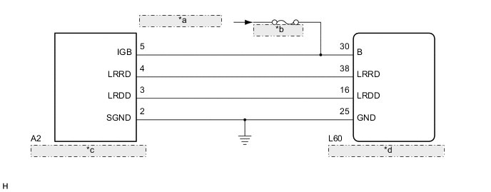
| *a | from IG1 NO. 1 Relay |
| *b | ECU-IG NO. 2 |
| *c | Millimeter Wave Radar Sensor |
| *d | Driving Support ECU Assembly |
CAUTION / NOTICE / HINT
Note
-
When replacing the millimeter wave radar sensor with a new one, make sure to perform Adjust Millimeter Wave Radar Sensor Assembly Click here.
-
Confirm that the connector is securely connected, as a partially connected connector is suspected for the cause of these DTCs.
PROCEDURE
-
CHECK DTC OUTPUT
-
Connect the GTS to the DLC3.
-
Turn the power switch on (IG).
-
Turn the GTS on.
-
Enter the following menus: Body Electrical / Pre-Crash and Pre-Crash 2 / Trouble Codes.
-
Check for DTCs.
Result Result Proceed to DTC U1104 is output A DTC U1104 is not output B
B 
GO TO CAN COMMUNICATION SYSTEM Click here
A 
-
-
CHECK HARNESS AND CONNECTOR (MILLIMETER WAVE RADAR SENSOR - DRIVING SUPPORT ECU)
-
Disconnect the L60 driving support ECU assembly connector.
-
Disconnect the A2 millimeter wave radar sensor connector.
-
Measure the resistance according to the value(s) in the table below.
Standard Resistance Tester Connection Condition Specified Condition A2-4 (LRRD) - L60-38 (LRRD) Always Below 1 Ω L60-38 (LRRD) - Body ground Always 10 kΩ or higher L60-25 (GND) - Body ground Always Below 1 Ω A2-2 (SGND) - Body ground Always Below 1 Ω -
Reconnect the L60 driving support ECU assembly connector.
-
Reconnect the A2 millimeter wave radar sensor connector.
NG
REPAIR OR REPLACE HARNESS OR CONNECTOR (DRIVING SUPPORT ECU - MILLIMETER WAVE RADAR SENSOR)
OK
-
-
CHECK CAN COMMUNICATION SYSTEM
-
Select "CAN Bus Check" from the "System Selection" on the GTS.
-
Select "Communication Malfunction DTC" from the "CAN Bus Check" screen, and then select "Enter".
OK CAN communication is normal.
NG
GO TO CAN COMMUNICATION SYSTEM Click here
OK
-
-
CHECK DRIVING SUPPORT ECU ASSEMBLY (B CIRCUIT)
-
Disconnect the A2 millimeter wave radar sensor connector.
-
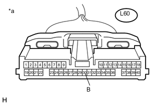
Text in Illustration *a Front view of wire harness connector
(to Driving Support ECU)
Disconnect the L60 driving support ECU assembly connector.
-
Turn the power switch on (IG).
-
Measure the voltage according to the value(s) in the table below.
Standard Voltage Tester Connection Condition Specified Condition L60-30 (B) - Body ground Power switch on (IG) 11 to 14 V
NG
REPAIR OR REPLACE HARNESS OR CONNECTOR (B CIRCUIT)
OK
-
-
CHECK MILLIMETER WAVE RADAR SENSOR (IGB CIRCUIT)
-
Turn the power switch on (IG).
-
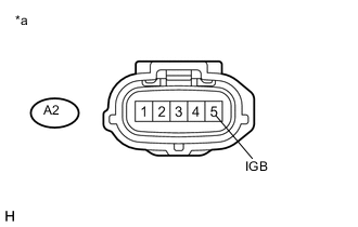
Text in Illustration *a Front view of wire harness connector
(to Millimeter Wave Radar Sensor)
Measure the voltage according to the value(s) in the table below.
Standard Voltage Tester Connection Condition Specified Condition A2-5 (IGB) - Body ground Power switch on (IG) 11 to 14 V -
Reconnect the A2 millimeter wave radar sensor connector.
NG
REPAIR OR REPLACE HARNESS OR CONNECTOR (IGB CIRCUIT)
OK
-
-
REPLACE MILLIMETER WAVE RADAR SENSOR
-
Replace the millimeter wave radar sensor Click here.
-
Adjust the millimeter wave radar sensor Click here.
NEXT
-
-
CHECK DTC OUTPUT
-
Clear the DTCs Click here.
-
Turn the cruise control main switch on.
-
Drive the vehicle at the required speed (45 km/h (28 mph) or higher).
-
Check if the same DTC is output Click here.
Result Result Proceed to DTC U1104 is not output A DTC U1104 is output B
A
END (MILLIMETER WAVE RADAR SENSOR WAS DEFECTIVE)
B
REPLACE DRIVING SUPPORT ECU ASSEMBLY Click here
-