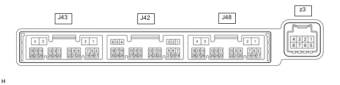
CLIMATE CONTROL SEAT SYSTEM TERMINALS OF ECU
-
CHECK AIR CONDITIONING AMPLIFIER ASSEMBLY
-
Disconnect the J43 air conditioning amplifier assembly connector.
-
Measure the voltage and resistance according to the value(s) in the table below.
Tech Tips
Measure the values on the wire harness side with the connector disconnected.
Terminal No. (Symbol) Wiring Color Terminal Description Condition Specified Condition J43-2 (IG+) - Body ground GR - Body ground Air conditioning amplifier power supply Engine switch off Below 1 V J43-2 (IG+) - Body ground GR - Body ground Air conditioning amplifier power supply Engine switch on (IG) 11 to 14 V J43-4 (GND) - Body ground W-B - Body ground Air conditioning amplifier ground Always Below 1 Ω -
Reconnect the J43 air conditioning amplifier assembly connector.
-
Check for pulses according to the value(s) in the table below.
Terminal No. (Symbol) Wiring Color Terminal Description Condition Specified Condition J43-24 (LOUT) - Body ground GR - Body ground Climate control blower control signal
-
Engine switch on (IG)
-
Refreshing seat switch (for LH) on
(blower position)
Pulse generation
(See waveform)
J43-23 (ROUT) - Body ground BE - Body ground Climate control blower control signal
-
Engine switch on (IG)
-
Refreshing seat switch (for RH) on
(blower position)
Pulse generation
(See waveform)
J43-14 (LIN1) - Body ground G - Body ground Refreshing seat switch signal Engine switch on (IG) Pulse generation
-
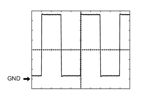
Waveform (Reference):
Measurement Condition Item Content Tester Connection
-
J43-24 (LOUT) - Body ground
-
J43-23 (ROUT) - Body ground
Tool Setting 1 V/DIV., 1 ms/DIV. Vehicle Condition
-
Engine switch on (IG)
-
Refreshing seat switch on
(blower position)
-
-
-
-
REFRESHING SEAT SWITCH

-
Disconnect the J82 refreshing seat switch connector.
-
Measure the voltage and resistance according to the value(s) in the table below.
Tech Tips
Measure the values on the wire harness side with the connector disconnected.
Terminal No. (Symbol) Wiring Color Terminal Description Condition Specified Condition J82-2 (IG) - Body ground L - Body ground Refreshing seat switch power supply Engine switch off Below 1 V J82-2 (IG) - Body ground L - Body ground Refreshing seat switch power supply Engine switch on (IG) 11 to 14 V J82-7 (E) - Body ground W-B - Body ground Refreshing seat switch ground Always Below 1 Ω -
Reconnect the J82 refreshing seat switch connector.
-
Check for pulses according to the value(s) in the table below.
Terminal No. (Symbol) Wiring Color Terminal Description Condition Specified Condition J82-4 (LIN1) - Body ground G - Body ground Refreshing seat switch signal Engine switch on (IG) Pulse generation
-