REAR CRANKSHAFT OIL SEAL REMOVAL

CAUTION / NOTICE / HINT
The necessary procedures (adjustment, calibration, initialization or registration) that must be performed after parts are removed and installed, or replaced during rear crankshaft oil seal removal/installation are shown below.
| Replaced Part or Performed Procedure | Necessary Procedure | Effect/Inoperative Function when Necessary Procedure not Performed | Link |
|---|---|---|---|
| Battery terminal is disconnected/reconnected | Perform steering sensor zero point calibration | Lane departure alert system (w/ Steering Control) | |
| Pre-collision system | |||
| Memorize steering angle neutral point | Parking assist monitor system | ||
| Panoramic View Monitor System | |||
| Replacement of ECM | Vehicle Identification Number (VIN) registration | MIL comes on | |
| Perform code registration (Immobiliser system) | Engine start function | See Service Bulletin for the registration method. | |
| Gas leak from exhaust system is repaired | Inspection after repair |
|
|
| Replacement of automatic transaxle assembly |
|
|
for Initialization for Registration |
| Replacement of ECM (If possible, read the transaxle compensation code from the previous ECM) |
|
||
| Replacement of ECM (If impossible, read the transaxle compensation code from the previous ECM) |
|
||
| Replacement of ECM | Perform code registration (Immobiliser function) |
|
See Service Bulletin for the registration method. |
| Suspension, tires, etc. (The vehicle height changes because of suspension or tire replacement) |
Rear television camera assembly optical axis (Back camera position setting) | Parking assist monitor system | for Initialization for Calibration |
|
Panoramic view monitor system | for Initialization for Calibration |
|
| Perform headlight ECU sub-assembly LH initialization | Lighting system (EXT) | ||
| Front wheel alignment adjustment | Perform system variant learning and acceleration sensor zero point calibration. |
|
*1: When the ECM is replaced with a new one, reset memory is unnecessary.
PROCEDURE
-
REMOVE AUTOMATIC TRANSAXLE ASSEMBLY
-
REMOVE DRIVE PLATE AND RING GEAR SUB-ASSEMBLY
-
Using height adjustment attachments and plate lift attachments, place the engine assembly on a flat level surface.
Note
-
Using height adjustment attachments and plate lift attachments, keep the engine assembly level.
-
To prevent the No. 2 oil pan sub-assembly from deforming, do not place any attachments under the No. 2 oil pan sub-assembly of the engine assembly.
-
Using an engine sling device and engine lift, secure the engine assembly before servicing.
-
-
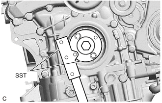
Using SST, hold the crankshaft pulley.
- SST
- 09213-70011 ( 09213-70020 )
- 09330-00021
-

Remove the 8 bolts, the rear drive plate spacer, the drive plate and ring gear sub-assembly.
-
-
REMOVE NO. 1 CRANKSHAFT POSITION SENSOR PLATE
-
Remove the No. 1 crankshaft position sensor plate.
-
-
REMOVE REAR ENGINE OIL SEAL
-
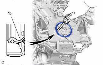
*a Protective Tape *b Cut Position Using a knife, cut through the lip of the rear engine oil seal.
-
Using a screwdriver with its tip wrapped with protective tape, pry out the rear engine oil seal.
Note
Be careful not to damage the crankshaft.
-