BLOCKING SYSTEM Engine does not Start
| DTC Code | DTC Name |
|---|---|
| Engine does not Start |
DESCRIPTION
If the engine does not start and no DTCs are output, the following conditions may apply:
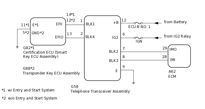
There is a short circuit between the telephone transceiver assembly and the certification ECU (smart key ECU assembly)*1 or transponder key ECU assembly*2.
The blocking system is set.
*1: w/ Entry and Start System
*2: w/o Entry and Start System
WIRING DIAGRAM
CAUTION / NOTICE / HINT
Before troubleshooting this symptom, make sure no immobiliser system DTCs or blocking system DTCs are output. If output, troubleshoot the immobiliser system DTCs or blocking system DTCs first.
When replacing the telephone transceiver assembly and certification ECU (smart key ECU assembly)*1 or transponder key ECU assembly*2, refer to the Service Bulletin.
When the telephone transceiver assembly is replaced, it is necessary to set the contract mode.
Inspect the fuses for circuits related to this system before performing the following inspection procedure.
*1: w/ Entry and Start System
*2: w/o Entry and Start System
PROCEDURE
CHECK DTC OUTPUT
Clear the DTCs.
Powertrain > Engine and ECT > Clear DTCs
Body Electrical > Entry&Start > Clear DTCs
Body Electrical > Immobiliser > Clear DTCs
Body Electrical > Telematics > Clear DTCs
Turn the ignition switch off.
Turn the ignition switch to ON.
After 10 seconds have elapsed, check for DTCs.
Powertrain > Engine and ECT > Trouble Codes
Body Electrical > Entry&Start > Trouble Codes
Body Electrical > Immobiliser > Trouble Codes
Body Electrical > Telematics > Trouble Codes
Result
Proceed to
DTC is not output.
A
SFI system (for 2AR-FE) DTC is output.
B
SFI system (for 3ZR-FE) DTC is output.
C
Immobiliser system (w/ Entry and Start System) DTC is output.
D
Immobiliser system (w/o Entry and Start System) DTC is output.
E
Entry and start system (for Start Function) DTC is output.
F
Blocking system DTC is output.
G
CHECK WHETHER ENGINE STARTS
Check that the engine starts normally.
OK
Engine starts normally.
Result
Proceed to
OK
NG
CHECK BLOCKING SYSTEM (SETTING)
Check the blocking system setting.
Tip:Check with the customer's contracted service provider to determine whether the blocking system is set.
Result
Proceed to
Blocking system is unset.
Blocking system is set.
Blocking system is set. UNSET BLOCKING SYSTEM
CHECK SECURITY INDICATOR LIGHT (IMMOBILISER SYSTEM UNSET)
w/ Entry and Start System:
Get into the vehicle while carrying an electrical key transmitter sub-assembly.
Press the engine switch with the brake pedal*1 or clutch pedal*2 released and check that the security indicator light changes from blinking to off at the same time the power source mode changes to on (ACC).
*1: except Manual Transaxle
*2: for Manual Transaxle
OK
Security indicator light changes from blinking to off at the same time the power source mode changes to on (ACC).
Tip:It is determined that the engine immobiliser function is operating correctly if the security indicator light changes from blinking to off at the same time that the power source mode changes to on (ACC).
w/o Entry and Start System:
Turn the ignition switch to ACC and check that the security indicator light changes from blinking to off at the same time the ignition switch is turned to ACC.
OK
Security indicator light changes from blinking to off at the same time the ignition switch is turned to ACC.
Tip:It is determined that the engine immobiliser function is operating correctly if the security indicator light changes from blinking to off at the same time the ignition switch is turned to ACC.
Result
Proceed to
OK
NG (w/ Entry and Start System)
NG (w/o Entry and Start System)
CHECK WHETHER ENGINE STARTS
Turn the ignition switch to ON.
After 5 seconds have elapsed, start the engine.
OK
Engine starts normally.
Result
Proceed to
OK
NG
CHECK TELEPHONE TRANSCEIVER ASSEMBLY
Using an oscilloscope, check the waveform.
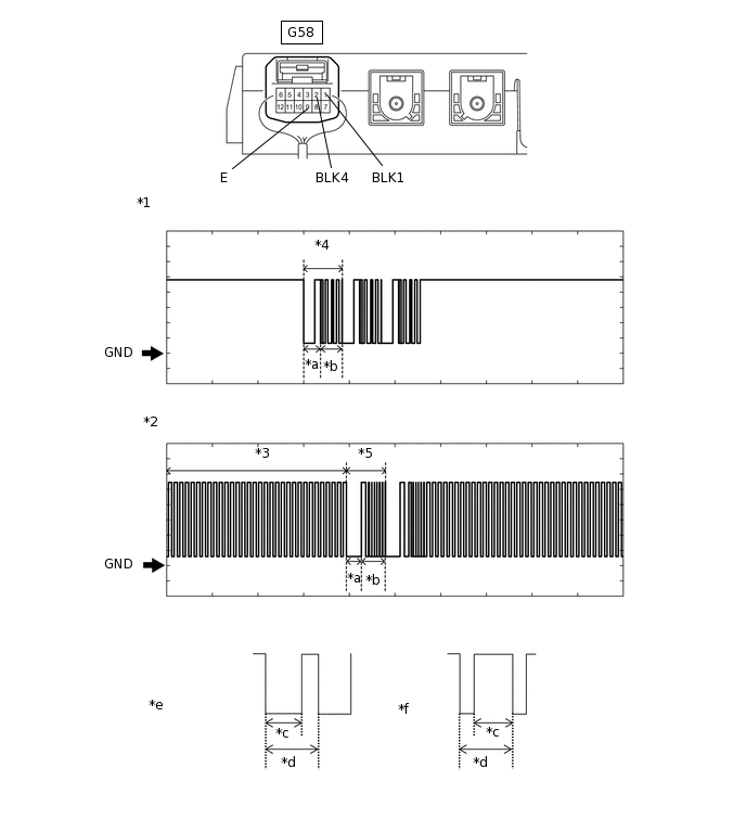
*1
Waveform 1
*2
Waveform 2
*3
Waveform A
*4
Waveform D
*5
Waveform E
-
-
*a
Approximately 160 ms
*b
Approximately 270 ms
*c
Approximately 40 ms
*d
Approximately 60 ms
*e
Details of waveform A
*f
or
Table 1. w/ Entry and Start System Tester Connection
Condition
Tool Setting
Specified Condition
G58-1 (BLK1) - G58-9 (E)
Check waveform within 3 seconds of starter operation and initial combustion, or within 3 seconds of engine switch first being turned on (IG) after cable disconnected and reconnected to negative (-) battery terminal.
2 V/DIV., 500 ms./DIV.
Pulse generation (See waveform 1)
G58-2 (BLK4) - G58-9 (E)
Check waveform within 3 seconds of starter operation and initial combustion, or within 3 seconds of engine switch first being turned on (IG) after cable disconnected and reconnected to negative (-) battery terminal.
2 V/DIV., 500 ms./DIV.
Pulse generation (See waveform 2)
Table 2. w/o Entry and Start System Tester Connection
Condition
Tool Setting
Specified Condition
G58-1 (BLK1) - G58-9 (E)
Check waveform within 3 seconds of starter operation and initial combustion, or within 3 seconds of ignition switch first being turned to ON after cable disconnected and reconnected to negative (-) battery terminal.
2 V/DIV., 500 ms./DIV.
Pulse generation (See waveform 1)
G58-2 (BLK4) - G58-9 (E)
Check waveform within 3 seconds of starter operation and initial combustion, or within 3 seconds of ignition switch first being turned to ON after cable disconnected and reconnected to negative (-) battery terminal.
2 V/DIV., 500 ms./DIV.
Pulse generation (See waveform 2)

*1
Waveform 1
*2
Waveform 2
*3
Waveform B
*4
Waveform C
*5
Waveform F
-
-
*a
Approximately 160 ms
*b
Approximately 270 ms
*c
Approximately 40 ms
*d
Approximately 60 ms
*e
Details of waveform B
*f
or
Table 3. w/ Entry and Start System Tester Connection
Condition
Tool Setting
Specified Condition
G58-7 (BLK2) - G58-9 (E)
Check waveform within 3 seconds of starter operation and initial combustion, or within 3 seconds of engine switch first being turned on (IG) after cable disconnected and reconnected to negative (-) battery terminal.
2 V/DIV., 500 ms./DIV.
Pulse generation (See waveform 1)
G58-8 (BLK3) - G58-9 (E)
Check waveform within 3 seconds of starter operation and initial combustion, or within 3 seconds of engine switch first being turned on (IG) after cable disconnected and reconnected to negative (-) battery terminal.
2 V/DIV., 500 ms./DIV.
Pulse generation (See waveform 2)
Table 4. w/o Entry and Start System Tester Connection
Condition
Tool Setting
Specified Condition
G58-8 (BLK3) - G58-9 (E)
Check waveform within 3 seconds of starter operation and initial combustion, or within 3 seconds of ignition switch first being turned to ON after cable disconnected and reconnected to negative (-) battery terminal
2 V/DIV., 500 ms./DIV.
Pulse generation (See waveform 1)
G58-8 (BLK3) - G58-9 (E)
Check waveform within 3 seconds of starter operation and initial combustion, or within 3 seconds of ignition switch first being turned to ON after cable disconnected and reconnected to negative (-) battery terminal
2 V/DIV., 500 ms./DIV.
Pulse generation (See waveform 2)
Note:The waveform shown in the illustration is an example for reference only. Noise, chattering, etc. are not shown.
Check if the waveforms are output in alphabetical order. If they are not, proceed to the step indicated for the incorrect waveform.
OK
The waveforms are output normally (refer to illustration).
Result
Result
Proceed to
OK (w/ Entry and Start System)
A
OK (w/o Entry and Start System)
B
Waveform A or E is abnormal (w/ Entry and Start System)
C
Waveform A or E is abnormal (w/o Entry and Start System)
D
Waveform B or F is abnormal
E
Waveform C is abnormal
F
Waveform D is abnormal (w/ Entry and Start System)
G
Waveform D is abnormal (w/o Entry and Start System)
H
B REREGISTRATIONClick here
C CHECK HARNESS AND CONNECTOR (TELEPHONE TRANSCEIVER ASSEMBLY - CERTIFICATION ECU [SMART KEY ECU ASSEMBLY])Click here
D CHECK HARNESS AND CONNECTOR (TELEPHONE TRANSCEIVER ASSEMBLY - TRANSPONDER KEY ECU ASSEMBLY)Click here
E CHECK HARNESS AND CONNECTOR (TELEPHONE TRANSCEIVER ASSEMBLY - ECM)Click here
F CHECK HARNESS AND CONNECTOR (TELEPHONE TRANSCEIVER ASSEMBLY - ECM)Click here
G CHECK HARNESS AND CONNECTOR (TELEPHONE TRANSCEIVER ASSEMBLY - CERTIFICATION ECU [SMART KEY ECU ASSEMBLY])Click here
H CHECK HARNESS AND CONNECTOR (TELEPHONE TRANSCEIVER ASSEMBLY - TRANSPONDER KEY ECU ASSEMBLY)Click here
REREGISTRATION
Reregister the communication ID.
Tip:Refer to the Service Bulletin.
Result
Proceed to
NEXT
CHECK WHETHER ENGINE STARTS
Check if the problem symptom occurs when the engine is started using a registered key.
OK
Engine starts normally.
Result
Proceed to
OK
NG
OK END
NG REPLACE CERTIFICATION ECU (SMART KEY ECU ASSEMBLY)Click here
REREGISTRATION
Reregister the communication ID.
Tip:Refer to the Service Bulletin.
Result
Proceed to
NEXT
CHECK WHETHER ENGINE STARTS
Check if the problem symptom occurs when the engine is started using a registered key.
OK
Engine starts normally.
Result
Proceed to
OK
NG
OK END
NG REPLACE TRANSPONDER KEY ECU ASSEMBLYClick here
CHECK HARNESS AND CONNECTOR (TELEPHONE TRANSCEIVER ASSEMBLY - CERTIFICATION ECU [SMART KEY ECU ASSEMBLY])
Disconnect the G58 telephone transceiver assembly connector.
Disconnect the G82 certification ECU (smart key ECU assembly) connector.
Measure the resistance according to the value(s) in the table below.
Standard Resistance
Tester Connection
Condition
Specified Condition
G58-2 (BLK4) - G82-13 (EFIO)
Always
Below 1 Ω
G58-2 (BLK4) - Body ground
Always
10 kΩ or higher
G82-13 (EFIO) - Body ground
Always
10 kΩ or higher
Result
Proceed to
OK
NG
NG REPAIR OR REPLACE HARNESS OR CONNECTOR
REPLACE CERTIFICATION ECU (SMART KEY ECU ASSEMBLY)
Replace the certification ECU (smart key ECU assembly) with a new one.
Tip:Refer to the Service Bulletin.
Result
Proceed to
NEXT
PERFORM REGISTRATION
Perform the registration.
Tip:Refer to the Service Bulletin.
Result
Proceed to
NEXT
CHECK WHETHER ENGINE STARTS
Check that the engine starts normally.
OK
Engine starts normally.
Result
Proceed to
OK
NG
OK END (CERTIFICATION ECU [SMART KEY ECU ASSEMBLY] WAS DEFECTIVE)
NG REPLACE TELEPHONE TRANSCEIVER ASSEMBLY
CHECK HARNESS AND CONNECTOR (TELEPHONE TRANSCEIVER ASSEMBLY - TRANSPONDER KEY ECU ASSEMBLY)
Disconnect the G58 telephone transceiver assembly connector.
Disconnect the G88 transponder key ECU assembly connector.
Measure the resistance according to the value(s) in the table below.
Standard Resistance
Tester Connection
Condition
Specified Condition
G58-2 (BLK4) - G88-13 (EFIO)
Always
Below 1 Ω
G58-2 (BLK4) - Body ground
Always
10 kΩ or higher
G88-13 (EFIO) - Body ground
Always
10 kΩ or higher
Result
Proceed to
OK
NG
NG REPAIR OR REPLACE HARNESS OR CONNECTOR
REPLACE TRANSPONDER KEY ECU ASSEMBLY
Replace the transponder key ECU assembly with a new one.
Tip:Refer to the Service Bulletin.
Result
Proceed to
NEXT
PERFORM REGISTRATION
Perform the registration.
Tip:Refer to the Service Bulletin.
Result
Proceed to
NEXT
CHECK WHETHER ENGINE STARTS
Check that the engine starts normally.
OK
Engine starts normally.
Result
Proceed to
OK
NG
OK END (TRANSPONDER KEY ECU ASSEMBLY WAS DEFECTIVE)
NG REPLACE TELEPHONE TRANSCEIVER ASSEMBLY
CHECK HARNESS AND CONNECTOR (TELEPHONE TRANSCEIVER ASSEMBLY - ECM)
Disconnect the G58 telephone transceiver assembly connector.
Disconnect the A62 ECM connector.
Measure the resistance according to the value(s) in the table below.
Standard Resistance
Tester Connection
Condition
Specified Condition
G58-8 (BLK3) - A62-28 (IMI)
Always
Below 1 Ω
G58-8 (BLK3) - Body ground
Always
10 kΩ or higher
A62-28 (IMI) - Body ground
Always
10 kΩ or higher
Result
Proceed to
OK
NG
NG REPAIR OR REPLACE HARNESS OR CONNECTOR
REPLACE TELEPHONE TRANSCEIVER ASSEMBLY
Temporarily replace the telephone transceiver assembly with a new one.
Tip:Refer to the Service Bulletin.
Result
Proceed to
NEXT
PERFORM REGISTRATION
Perform the registration.
Tip:Refer to the Service Bulletin.
Result
Proceed to
NEXT
CHECK WHETHER ENGINE STARTS
Check that the engine starts normally.
OK
Engine starts normally.
Result
Proceed to
OK
NG
OK END (TELEPHONE TRANSCEIVER ASSEMBLY WAS DEFECTIVE)
REPLACE ECM
Temporarily replace the ECM with a new one.
for 2AR-FE
for 3ZR-FE
Tip:Refer to the Service Bulletin.
Result
Proceed to
NEXT
CHECK DTC OUTPUT
Clear the DTCs.
Powertrain > Engine and ECT > Clear DTCs
Body Electrical > Entry&Start > Clear DTCs
Body Electrical > Immobiliser > Clear DTCs
Body Electrical > Telematics > Clear DTCs
Turn the ignition switch off.
Turn the ignition switch to ON.
After 10 seconds have elapsed, check for DTCs.
Powertrain > Engine and ECT > Trouble Codes
Body Electrical > Entry&Start > Trouble Codes
Body Electrical > Immobiliser > Trouble Codes
Body Electrical > Telematics > Trouble Codes
Result
Proceed to
DTC is not output.
A
SFI system (for 2AR-FE) DTC is output.
B
SFI system (for 3ZR-FE) DTC is output.
C
Immobiliser system (w/ Entry and Start System) DTC is output.
D
Immobiliser system (w/o Entry and Start System) DTC is output.
E
Entry and start system (for Start Function) DTC is output.
F
Blocking system DTC is output.
G
A END (POWER MANAGEMENT CONTROL ECU WAS DEFECTIVE)
CHECK HARNESS AND CONNECTOR (TELEPHONE TRANSCEIVER ASSEMBLY - ECM)
Disconnect the G58 telephone transceiver assembly connector.
Disconnect the A62 ECM connector.
Measure the resistance according to the value(s) in the table below.
Standard Resistance
Tester Connection
Condition
Specified Condition
G58-7 (BLK2) - A62-29 (IMO)
Always
Below 1 Ω
G58-7 (BLK2) - Body ground
Always
10 kΩ or higher
A62-29 (IMO) - Body ground
Always
10 kΩ or higher
Result
Proceed to
OK
NG
NG REPAIR OR REPLACE HARNESS OR CONNECTOR
REPLACE ECM
Temporarily replace the ECM with a new one.
for 2AR-FE
for 3ZR-FE
Tip:Refer to the Service Bulletin.
Result
Proceed to
NEXT
CHECK DTC OUTPUT
Clear the DTCs.
Powertrain > Engine and ECT > Clear DTCs
Body Electrical > Entry&Start > Clear DTCs
Body Electrical > Immobiliser > Clear DTCs
Body Electrical > Telematics > Clear DTCs
Turn the ignition switch off.
Turn the ignition switch to ON.
After 10 seconds have elapsed, check for DTCs.
Powertrain > Engine and ECT > Trouble Codes
Body Electrical > Entry&Start > Trouble Codes
Body Electrical > Immobiliser > Trouble Codes
Body Electrical > Telematics > Trouble Codes
Result
Proceed to
DTC is not output.
A
SFI system (for 2AR-FE) DTC is output.
B
SFI system (for 3ZR-FE) DTC is output.
C
Immobiliser system (w/ Entry and Start System) DTC is output.
D
Immobiliser system (w/o Entry and Start System) DTC is output.
E
Entry and start system (for Start Function) DTC is output.
F
Blocking system DTC is output.
G
CHECK WHETHER ENGINE STARTS
Check that the engine starts normally.
OK
Engine starts normally.
Result
Proceed to
OK
NG
OK END (ECM WAS DEFECTIVE)
NG REPLACE TELEPHONE TRANSCEIVER ASSEMBLY
CHECK HARNESS AND CONNECTOR (TELEPHONE TRANSCEIVER ASSEMBLY - CERTIFICATION ECU [SMART KEY ECU ASSEMBLY])
Disconnect the G58 telephone transceiver assembly connector.
Disconnect the G82 certification ECU (smart key ECU assembly) connector.
Measure the resistance according to the value(s) in the table below.
Standard Resistance
Tester Connection
Condition
Specified Condition
G58-1 (BLK1) - G82-14 (EFII)
Always
Below 1 Ω
G58-1 (BLK1) - Body ground
Always
10 kΩ or higher
G82-14 (EFII) - Body ground
Always
10 kΩ or higher
Result
Proceed to
OK
NG
NG REPAIR OR REPLACE HARNESS OR CONNECTOR
REPLACE TELEPHONE TRANSCEIVER ASSEMBLY
Temporarily replace the telephone transceiver assembly with a new one.
Tip:Refer to the Service Bulletin.
Result
Proceed to
NEXT
PERFORM REGISTRATION
Perform the registration.
Tip:Refer to the Service Bulletin.
Result
Proceed to
NEXT
CHECK WHETHER ENGINE STARTS
Check that the engine starts normally.
OK
Engine starts normally.
Result
Proceed to
OK
NG
OK END (TELEPHONE TRANSCEIVER ASSEMBLY WAS DEFECTIVE)
NG REPLACE CERTIFICATION ECU (SMART KEY ECU ASSEMBLY)
CHECK HARNESS AND CONNECTOR (TELEPHONE TRANSCEIVER ASSEMBLY - TRANSPONDER KEY ECU ASSEMBLY)
Disconnect the G58 telephone transceiver assembly connector.
Disconnect the G88 transponder key ECU assembly connector.
Measure the resistance according to the value(s) in the table below.
Standard Resistance
Tester Connection
Condition
Specified Condition
G58-1 (BLK1) - G88-12 (EFII)
Always
Below 1 Ω
G58-1 (BLK1) - Body ground
Always
10 kΩ or higher
G88-12 (EFII) - Body ground
Always
10 kΩ or higher
Result
Proceed to
OK
NG
NG REPAIR OR REPLACE HARNESS OR CONNECTOR
REPLACE TELEPHONE TRANSCEIVER ASSEMBLY
Temporarily replace the telephone transceiver assembly with a new one.
Tip:Refer to the Service Bulletin.
Result
Proceed to
NEXT
PERFORM REGISTRATION
Perform the registration.
Tip:Refer to the Service Bulletin.
Result
Proceed to
NEXT
CHECK WHETHER ENGINE STARTS
Check that the engine starts normally.
OK
Engine starts normally.
Result
Proceed to
OK
NG
OK END (TELEPHONE TRANSCEIVER ASSEMBLY WAS DEFECTIVE)
NG REPLACE TRANSPONDER KEY ECU ASSEMBLY