STEERING COLUMN ASSEMBLY REASSEMBLY
CAUTION / NOTICE / HINT
When using a vise, place aluminum plates between the part and vise.
When using a vise, do not overtighten it.
PROCEDURE
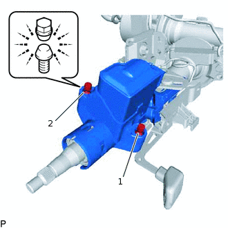
INSTALL POWER STEERING MOTOR ASSEMBLY
Apply grease to the spline part of the electric power steering column sub-assembly.
Install a new O-ring to the power steering motor assembly.
-
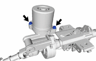
Install the power steering motor assembly with the new 2 bolts.
20 N*m
204 kgf*cm
15 ft.*lbf
Place new heat resistant tape.
Note:As heat from the power steering motor assembly may generate smoke, use heat resistant tape (resistant to 100°C (212°F) or higher).
INSTALL POWER STEERING ECU ASSEMBLY
INSTALL IGNITION SWITCH LOCK CYLINDER ASSEMBLY (w/o Entry and Start System)
-
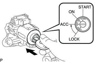
Turn the ignition switch to ACC.
Install the ignition switch lock cylinder assembly into the upper steering column bracket assembly.
Make sure that the ignition switch lock cylinder assembly is securely fixed onto the ignition switch lock cylinder assembly.
-
INSTALL UNLOCK WARNING SWITCH ASSEMBLY (w/o Entry and Start System)
-
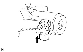
Attach the 2 claws to install the unlock warning switch assembly onto the upper steering column bracket assembly.
Tip:Slide the unlock warning switch assembly in the direction shown by the arrow in the illustration to install it.
-
INSTALL KEY INTERLOCK SOLENOID (for Automatic Transaxle and CVT)
-
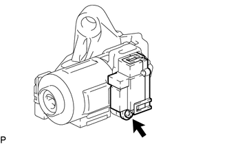
Install the key interlock solenoid onto the upper steering column bracket assembly with the screw.
-
INSTALL IGNITION OR STARTER SWITCH ASSEMBLY (w/o Entry and Start System)
INSTALL TRANSPONDER KEY COIL (w/o Entry and Start System)
INSTALL STEERING LOCK ACTUATOR ASSEMBLY (w/ Entry and Start System)
Tip:When replacing the steering lock actuator assembly, refer to the Service Bulletin.
Temporarily install the steering lock actuator assembly with 2 new tapered-head bolts.
Note:Be sure to use 2 new tapered-head bolts.
-
Tighten the 2 tapered-head bolts until the bolt head breaks off.
Tip:Tighten the nuts in the order shown in the illustration.
INSTALL STEERING LOCK ACTUATOR ASSEMBLY (w/o Entry and Start System)
Tip:Refer to "INSTALL STEERING LOCK ACTUATOR ASSEMBLY (w/ Entry and Start System)"