POWER MANAGEMENT CONTROL ECU REMOVAL
PROCEDURE
-
PRECAUTION
Note
After turning the power switch off, waiting time may be required before disconnecting the cable from the negative (-) auxiliary battery terminal. Therefore, make sure to read the disconnecting the cable from the negative (-) auxiliary battery terminal notices before proceeding with work Click here.
-
WHEN REPLACING POWER MANAGEMENT CONTROL ECU
HV battery learning values are stored in the power management control ECU and ECM to illuminate the hybrid battery indicator light in the combination meter assembly. When either of these ECUs is replaced, the new ECU receives the HV battery learning value data from the other ECU and updates the information.
Note
-
Do not replace the power management control ECU and ECM at the same time as it clears the HV battery learning values. However, if it is necessary to replace both ECUs at the same time, replace them by following the procedure below.
-
Do not replace the power management control ECU or ECM with used ones from other vehicles.
-
Procedure when replacing both power management control ECU and ECM:
-
Disconnect the cable from the negative (-) auxiliary battery terminal.
-
Replace either of the ECUs.
-
Connect the cable to the negative (-) auxiliary battery terminal.
-
Turn the power switch on (READY) and wait for 5 minutes or more.
-
Turn the power switch off and disconnect the cable from the negative (-) auxiliary battery terminal.
-
Replace the other ECU.
-
Connect the cable to the negative (-) auxiliary battery terminal.
-
Check that the power switch can be turned on (READY).
Tech Tips
If the power management control ECU and ECM are replaced at the same time without following the above procedure, replace either of the ECUs with its original one and then replace it again by following the above procedure. If the correct procedure is not followed, perform the procedure again from the beginning.
-
-
-
REMOVE DECK BOARD ASSEMBLY
-
REMOVE NO. 1 DECK BOARD
-
REMOVE NO. 2 DECK BOARD
-
REMOVE REAR DECK FLOOR BOX
-
REMOVE DECK FLOOR BOX RH
-
DISCONNECT CABLE FROM NEGATIVE AUXILIARY BATTERY TERMINAL
Note
When disconnecting the cable, some systems need to be initialized after the cable is reconnected Click here.
-
REMOVE NO. 2 INSTRUMENT PANEL UNDER COVER SUB-ASSEMBLY
-
REMOVE GLOVE COMPARTMENT DOOR ASSEMBLY
-
REMOVE ECU INTEGRATION BOX RH (for LHD)
-
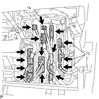
Text in Illustration *A w/ Pre-crash System *B w/ Dynamic Radar Cruise Control System *C w/ Advanced Parking Guidance System Disconnect each connector.
-
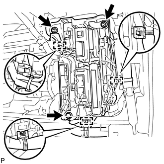
Disengage the 3 clamps.
-
Remove the bolt and 2 nuts, and ECU integration box RH.
-
-
REMOVE ECU INTEGRATION BOX LH (for RHD)
-
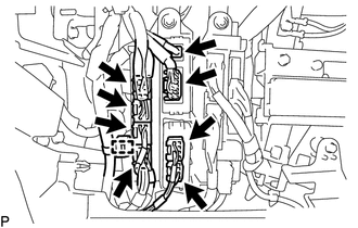
Disconnect each connector.
-
Disengage the clamp.
-
Remove the bolt and nut, and ECU integration box LH.
-
-
REMOVE POWER MANAGEMENT CONTROL ECU
-
for LHD:
-
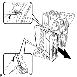
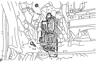
Using a screwdriver, disengage the 2 claws and remove the power management control ECU as shown in the illustration.
-
-
for RHD:
-
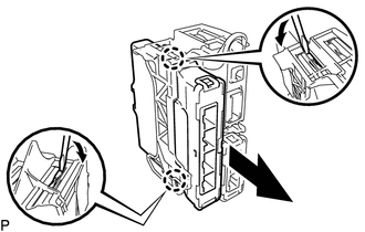
Using a screwdriver, disengage the 2 claws and remove the power management control ECU as shown in the illustration.
-
-