CANVAS TOP SYSTEM Canvas Top System does not Operate
| DTC Code | DTC Name |
|---|---|
| Canvas Top System does not Operate |
DESCRIPTION
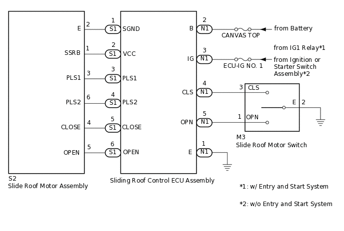
The sliding roof control ECU assembly receives open and close signals when the slide roof motor switch is operated and drives the slide roof motor assembly.
WIRING DIAGRAM
CAUTION / NOTICE / HINT
Inspect the fuses for circuits related to this system before performing the following procedure.
Check that the fail-safe function (thermal protection) does not operate before performing troubleshooting. Check the operation of the canvas top after the vehicle has been stopped for 5 minutes with the ignition switch ON.
If the sliding roof control ECU assembly or slide roof motor assembly is removed and reinstalled or replaced, the sliding roof control ECU assembly must be initialized.
PROCEDURE
CHECK HARNESS AND CONNECTOR (SLIDING ROOF CONTROL ECU ASSEMBLY - BATTERY AND BODY GROUND)
-
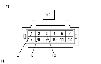
*a
Front view of wire harness connector
(to Sliding Roof Control ECU Assembly)
Disconnect the N1 sliding roof control ECU assembly connector.
Measure the voltage according to the value(s) in the table below.
Standard Voltage
Tester Connection
Condition
Specified Condition
N1-2 (B) - Body ground
Always
11 to 14 V
N1-3 (IG) - Body ground
Ignition switch ON
11 to 14 V
Measure the resistance according to the value(s) in the table below.
Standard Resistance
Tester Connection
Condition
Specified Condition
N1-1 (E) - Body ground
Always
Below 1 Ω
Result
Proceed to
OK
NG
NG REPAIR OR REPLACE HARNESS OR CONNECTOR
-
INSPECT SLIDE ROOF MOTOR SWITCH
Remove the slide roof motor switch.
Inspect the slide roof motor switch.
Result
Proceed to
OK
NG
CHECK HARNESS AND CONNECTOR (SLIDING ROOF CONTROL ECU ASSEMBLY - SLIDE ROOF MOTOR SWITCH AND BODY GROUND)
Measure the resistance according to the value(s) in the table below.
Standard Resistance
Tester Connection
Condition
Specified Condition
N1-4 (CLS) - M3-3 (CLS)
Always
Below 1 Ω
N1-4 (CLS) or M3-3 (CLS) - Body ground
Always
10 kΩ or higher
N1-5 (OPN) - M3-1 (OPN)
Always
Below 1 Ω
N1-5 (OPN) or M3-1 (OPN) - Body ground
Always
10 kΩ or higher
M3-2 (E) - Body ground
Always
10 kΩ or higher
Result
Proceed to
OK
NG
NG REPAIR OR REPLACE HARNESS OR CONNECTOR
INSPECT SLIDE ROOF MOTOR ASSEMBLY
Remove the slide roof motor assembly.
Inspect the slide roof motor assembly.
Result
Proceed to
OK
NG
CHECK HARNESS AND CONNECTOR (SLIDING ROOF CONTROL ECU ASSEMBLY - SLIDE ROOF MOTOR ASSEMBLY)
Disconnect the S1 sliding roof control ECU assembly connector.
Measure the resistance according to the value(s) in the table below.
Standard Resistance
Tester Connection
Condition
Specified Condition
S1-1 (SGND) - S2-2 (E)
Always
Below 1 Ω
S1-1 (SGND) or S2-2 (E) - Body ground
Always
10 kΩ or higher
S1-2 (VCC) - S2-1 (SSRB)
Always
Below 1 Ω
S1-2 (VCC) or S2-1 (SSRB) - Body ground
Always
10 kΩ or higher
S1-3 (PLS1) - S2-3 (PLS1)
Always
Below 1 Ω
S1-3 (PLS1) or S2-3 (PLS1) - Body ground
Always
10 kΩ or higher
S1-4 (PLS2) - S2-6 (PLS2)
Always
Below 1 Ω
S1-4 (PLS2) or S2-6 (PLS2) - Body ground
Always
10 kΩ or higher
S1-5 (CLOSE) - S2-4 (CLOSE)
Always
Below 1 Ω
S1-5 (CLOSE) or S2-4 (CLOSE) - Body ground
Always
10 kΩ or higher
S1-6 (OPEN) - S2-5 (OPEN)
Always
Below 1 Ω
S1-6 (OPEN) or S2-5 (OPEN) - Body ground
Always
10 kΩ or higher
Result
Proceed to
OK
NG
NG REPAIR OR REPLACE HARNESS OR CONNECTOR