CAN COMMUNICATION SYSTEM(w/o Central Gateway ECU) SYSTEM DIAGRAM
OVERALL CAN BUS DIAGRAM
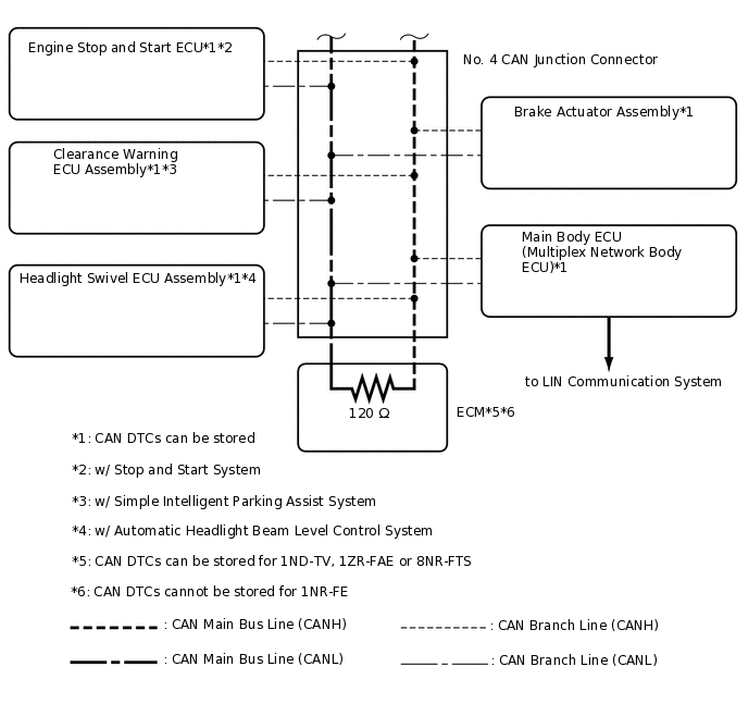
The CAN communication system is composed of 1 bus.
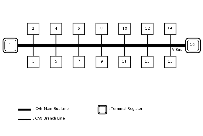
1
Combination Meter Assembly
2
Certification ECU (Smart Key ECU Assembly)
(w/ Entry and Start System)
3
Steering Sensor (Spiral Cable with Sensor Sub-assembly)
(w/ VSC)
4
Radio and Display Receiver Assembly
(for Radio and Display Type)
5
Airbag Sensor Assembly
6
Power Steering ECU Assembly
7
Air Conditioning Amplifier Assembly
(w/ Air Conditioning System)
8
Clearance Warning ECU Assembly
(w/ Simple Intelligent Parking Assist System)
9
Engine Stop and Start ECU
(w/ Stop and Start System)
10
Brake Actuator Assembly
11
DLC3
12
Main Body ECU (Multiplex Network Body ECU)
13
Headlight Leveling ECU Assembly
(for Sedan with Automatic Headlight Beam Level Control System)
Headlight Swivel ECU Assembly
(except Sedan with Automatic Headlight Beam Level Control System)
14
Pre-crash Safety City Sensor
(w/ Toyota Safety Sense)
15
Telematics Transceiver
(w/ Manual (SOS) Switch)
16
ECM
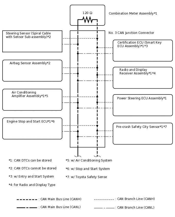
Tip:Refer to the following bus wiring diagrams for details.
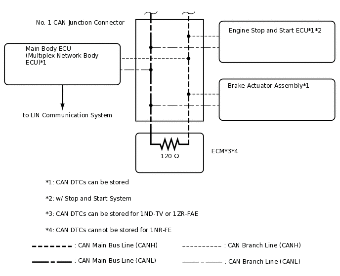
V BUS (for LHD Sedan)
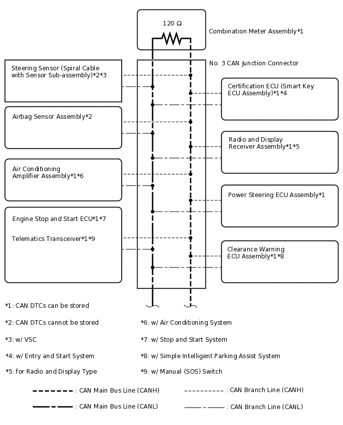
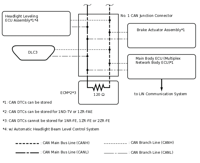 Tip:
Tip:The CAN communication system connects to other networks via ECUs that function as a gateway.
V BUS (for LHD except Sedan)
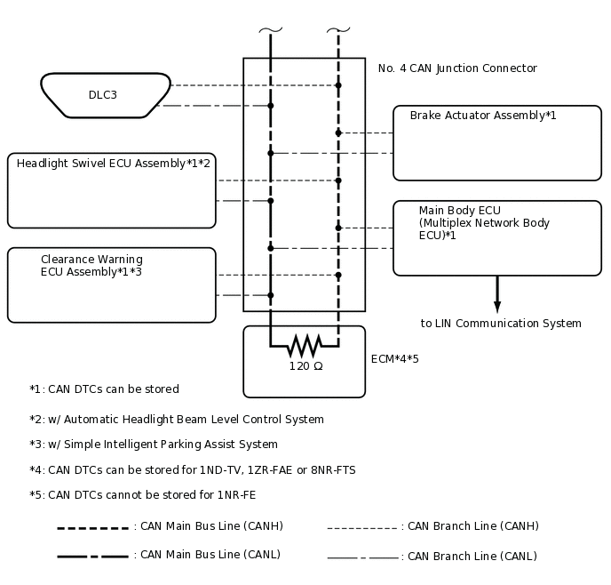 Tip:
Tip:The CAN communication system connects to other networks via ECUs that function as a gateway.
V BUS (for RHD Sedan)
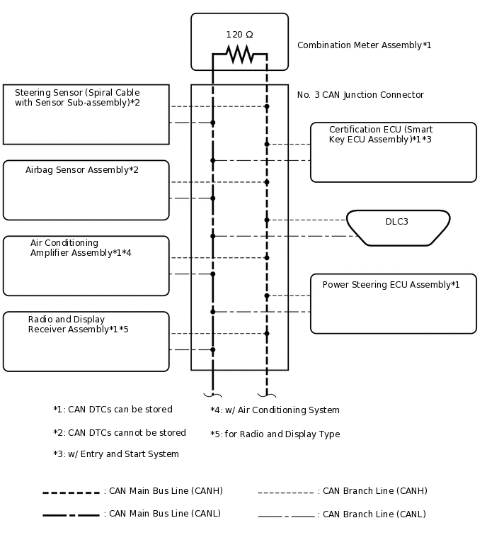
 Tip:
Tip:The CAN communication system connects to other networks via ECUs that function as a gateway.
V BUS (for RHD except Sedan)
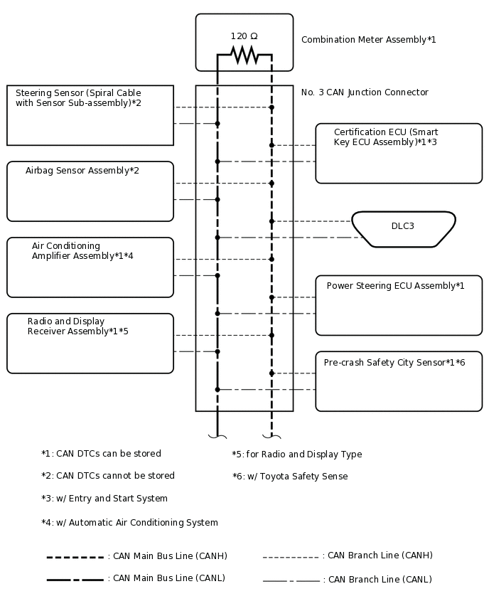
 Tip:
Tip:The CAN communication system connects to other networks via ECUs that function as a gateway.