ENGINE ASSEMBLY REMOVAL
CAUTION / NOTICE / HINT
The necessary procedures (adjustment, calibration, initialization or registration) that must be performed after parts are removed and installed, or replaced during engine assembly removal/installation are shown below.
| Replaced Part or Performed Procedure | Necessary Procedure | Effect/Inoperative Function when Necessary Procedure not Performed | Link |
|---|---|---|---|
| Battery terminal is disconnected/reconnected | Perform steering sensor zero point calibration | Lane departure alert system (w/ Steering Control) | |
| Pre-collision system | |||
| Memorize steering angle neutral point | Parking Assist Monitor System | ||
| Panoramic View Monitor System | |||
| Replacement of ECM | Vehicle Identification Number (VIN) registration | MIL comes on | |
| Perform code registration (Immobiliser system) | Engine start function | See Service Bulletin for the registration method. | |
|
Inspection after repair |
|
|
| Replacement of automatic transaxle assembly |
|
|
for Initialization for Registration |
| Replacement of ECM (If possible, read the transaxle compensation code from the previous ECM) |
|
||
| Replacement of ECM (If impossible, read the transaxle compensation code from the previous ECM) |
|
||
| Replacement of ECM | Perform code registration (Immobiliser function) |
|
See Service Bulletin for the registration method. |
| Suspension, tires, etc. (The vehicle height changes because of suspension or tire replacement) |
Rear television camera assembly optical axis (Back camera position setting) | Parking assist monitor system | for Initialization for Calibration |
|
Panoramic view monitor system | for Initialization for Calibration |
|
| Perform headlight ECU sub-assembly LH initialization | Lighting system (EXT) | ||
| Front wheel alignment adjustment | Perform system variant learning and acceleration sensor zero point calibration. |
|
*1: When the ECM is replaced with a new one, reset memory is unnecessary.
CAUTION:
-
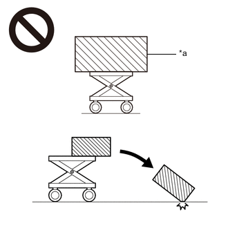
*a An Object Exceeding Weight Limit of Engine Lifter The engine assembly with transaxle is very heavy. Be sure to follow the procedure described in the repair manual, or the engine lifter may suddenly drop or the engine assembly with transaxle may fall off the engine lifter.
-
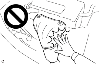
To prevent burns, do not touch the engine, exhaust manifold or other high temperature components while the engine is hot.
PROCEDURE
-
PRECAUTION
Note
After turning the engine switch off, waiting time may be required before disconnecting the cable from the negative (-) battery terminal. Therefore, make sure to read the disconnecting the cable from the negative (-) battery terminal notices before proceeding with work.
-
RECOVER REFRIGERANT FROM REFRIGERATION SYSTEM
-
DISCHARGE FUEL SYSTEM PRESSURE
-
DISCONNECT CABLE FROM NEGATIVE BATTERY TERMINAL
Note
When disconnecting the cable, some systems need to be initialized after the cable is reconnected.
-
ALIGN FRONT WHEELS FACING STRAIGHT AHEAD
-
SECURE STEERING WHEEL
-
REMOVE FRONT WHEEL OPENING EXTENSION PAD LH
-
Remove the 3 screws and front wheel opening extension pad LH.
-
-
REMOVE FRONT WHEEL OPENING EXTENSION PAD RH
-
Remove the 3 screws and front wheel opening extension pad RH.
-
-
REMOVE NO. 1 ENGINE UNDER COVER
-
Remove the bolt, 2 clips, 6 screws and No. 1 engine under cover.
-
-
REMOVE FRONT FENDER APRON SEAL LH
-
Remove the 2 screws, clip and front fender apron seal LH from the vehicle body.
-
-
REMOVE FRONT FENDER APRON SEAL RH
-
Remove the 2 screws, clip and front fender apron seal RH from the vehicle body.
-
-
REMOVE FRONT BUMPER COVER
-
REMOVE FRONT LOWER BUMPER ABSORBER
-
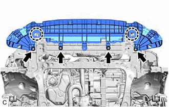
Remove the 4 bolts.
-
Disengage the 2 claws to remove the front lower bumper absorber.
-
-
DRAIN ENGINE COOLANT
-
DRAIN ENGINE OIL
-
DRAIN AUTOMATIC TRANSAXLE FLUID
-
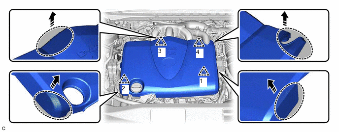
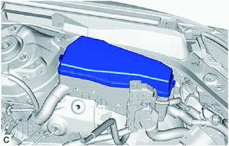
REMOVE V-BANK COVER SUB-ASSEMBLY
-
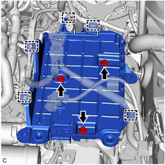
Disengage the 4 clips in the order shown in the illustration and lift the V-bank cover sub-assembly upward to remove it.

Hold here 
Pull in this Direction Note
-
Pull the V-bank cover sub-assembly straight up to remove it.
-
Do not remove the V-bank cover sub-assembly in any direction other than upward. If the V-bank cover sub-assembly is removed in any direction other than upward, it may be damaged.
-
If the clips are not disengaged in the order shown in the illustration, the V-bank cover sub-assembly may be damaged.
-
-
-
REMOVE INLET AIR CLEANER ASSEMBLY
-
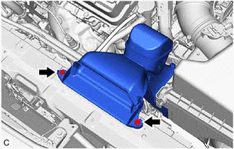
Remove the 2 bolts and inlet air cleaner assembly.
-
-
REMOVE AIR CLEANER ASSEMBLY WITH AIR CLEANER HOSE
-
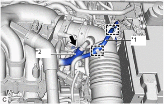
*1 No. 1 Fuel Vapor Feed Hose *2 No. 2 Ventilation Hose Disengage the 2 clamps to disconnect the No. 1 fuel vapor feed hose from the air cleaner hose.
-
Slide the clip and disconnect the No. 2 ventilation hose from the air cleaner hose.
-
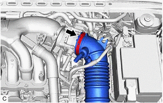
Loosen the hose clamp.
-
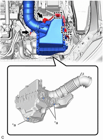
*a Pin Disconnect the mass air flow meter sub-assembly connector.
-
Disengage the 3 wire harness clamps.
-
Disconnect the vacuum hose from the air cleaner hose.
-
Disengage the 3 pins and remove the air cleaner assembly with air cleaner hose.
Note
Make sure the air cleaner support remains attached to the vehicle body.
-
-
REMOVE ECM
-
DISCONNECT ENGINE ROOM MAIN WIRE
-
Remove the nut and disconnect the engine wire with engine room main wire from the positive (+) battery terminal.
-
-
REMOVE BATTERY
-
REMOVE BATTERY CLAMP SUB-ASSEMBLY
-
Disengage the 5 clamps from the battery clamp sub-assembly.
-
Remove the 3 bolts and battery clamp sub-assembly.
-
-
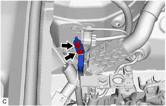
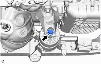
DISCONNECT TRANSMISSION CONTROL CABLE ASSEMBLY
-
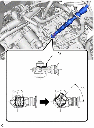
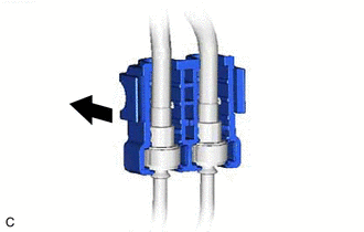
*a Clip *b 45° to 60° While disengaging the clip as shown in the illustration, disconnect the transmission control cable assembly from the transmission control shaft lever together with the clip.
-
Remove the clip and disconnect the transmission control cable assembly from the No. 1 transmission control cable bracket.
-
-
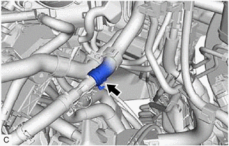
DISCONNECT NO. 1 FUEL VAPOR FEED HOSE
-
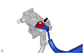
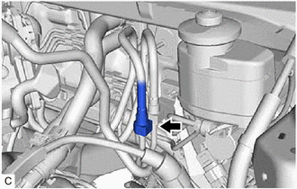
Slide the clip and disconnect the No. 1 fuel vapor feed hose from the No. 1 vacuum switching valve assembly.
-
-
DISCONNECT UNION TO CHECK VALVE HOSE
-
for LHD:
-
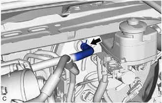
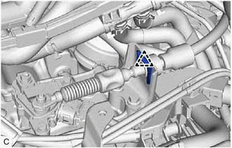
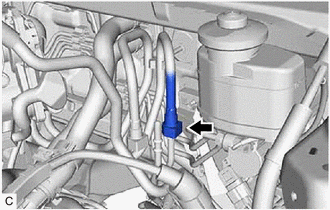
Slide the clip and disconnect the union to check valve hose from the brake booster assembly.
-
-
for RHD:
-
Slide the clip and disconnect the union to check valve hose from the brake booster assembly.
-
-
-
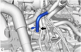
DISCONNECT NO. 2 RADIATOR HOSE
-
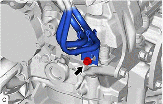
Slide the clip and disconnect the No. 2 radiator hose from the water inlet.
-
-
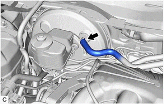
SEPARATE RADIATOR HOSE SUB-ASSEMBLY
-
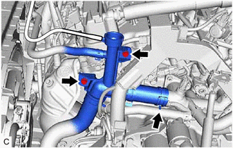
Slide the clip and disconnect the radiator hose sub-assembly from the water outlet.
-
Remove the 2 bolts and separate the radiator hose sub-assembly from the engine assembly.
-
-
DISCONNECT INLET HEATER WATER HOSE
-
Disengage the clamp.
-
Slide the clip and disconnect the inlet heater water hose from the water outlet.
-
-
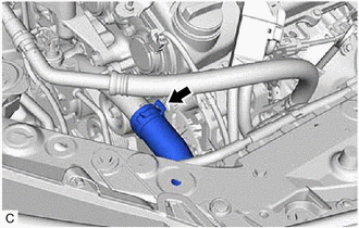
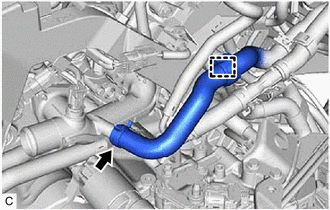
DISCONNECT OUTLET HEATER WATER HOSE
-
Slide the clip and disconnect the outlet heater water hose from the heater water pipe.
-
-
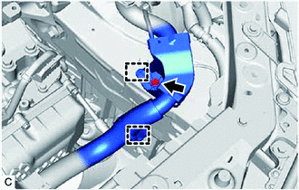
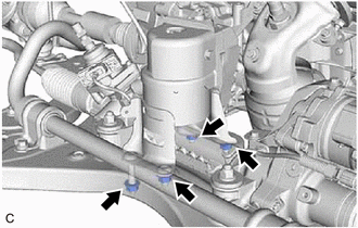
DISCONNECT NO. 1 FUEL HOSE
-
Disengage the 2 claws to remove the No. 2 fuel pipe clamp.
-
Remove the No. 1 fuel pipe clamp from the fuel tube connector.
-
Disconnect the No. 1 fuel hose (for Port Injection).
-
Disconnect the No. 1 fuel hose from the fuel pipe.
-
-
Disconnect the No. 1 fuel hose (for Direct Injection).
-
Disconnect the No. 1 fuel hose from the fuel pipe.
-
-
Separate the bolt and disengage the No. 1 fuel hose.
-
-
DISCONNECT NO. 1 COOLER REFRIGERANT DISCHARGE HOSE SUB-ASSEMBLY
-
DISCONNECT SUCTION HOSE SUB-ASSEMBLY
-
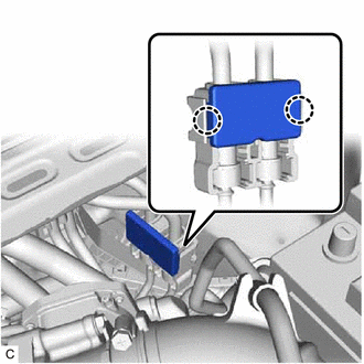
DISCONNECT ENGINE WIRE
Tech Tips
After disconnecting the engine wire, secure it with tape or equivalent to keep it out of the way.
-
Remove the No. 2 relay block cover from the engine room relay block and junction block assembly.
-
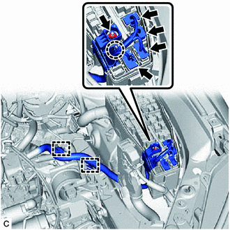
Remove the nut from the engine room relay block and junction block assembly.
-
Disconnect the 4 connectors from the engine room relay block and junction block assembly.
-
Disengage the 2 clamps.
-
Using a screwdriver, disengage the claw and disconnect the engine wire from the engine room relay block and junction block assembly.
-
Remove the bolt.
-
Disengage the 2 clamps and disconnect the engine wire from the vehicle body.
-
-
DISCONNECT EARTH WIRE
-
Remove the 2 bolts and disconnect the earth wire from the vehicle body.
-
-
SEPARATE STEERING INTERMEDIATE SHAFT ASSEMBLY
-
REMOVE EXHAUST MANIFOLD
-
REMOVE FRONT DRIVE SHAFT ASSEMBLY
-
REMOVE NO. 1 EXHAUST PIPE SUPPORT BRACKET (for Upper Side)
-
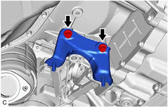
Remove the 2 bolts and No. 1 exhaust pipe support bracket from the oil pan sub-assembly.
-
-
REMOVE FLYWHEEL HOUSING UNDER COVER
-
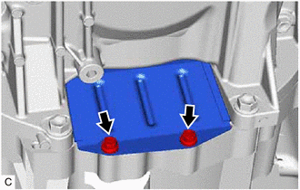
Remove the 2 bolts and flywheel housing under cover.
-
-
REMOVE DRIVE PLATE AND TORQUE CONVERTER ASSEMBLY SETTING BOLT
-
REMOVE ENGINE ASSEMBLY WITH TRANSAXLE
-
Set an engine lifter.
Note
-
Using height adjustment attachments and plate lift attachments, keep the engine assembly with transaxle level.
-
Do not perform any procedures while the engine assembly is suspended because doing so may cause the engine assembly to drop, resulting in injury. However, the engine assembly needs to be suspended when it is installed to or removed from an engine stand.
-
To prevent the engine assembly from unexpectedly moving, securely support the engine assembly until it is secured to an engine stand.
-
To prevent the No. 2 oil pan sub-assembly from deforming, do not place any attachments under the No. 2 oil pan sub-assembly of the engine assembly with transaxle.
-
-

Remove the bolt, 2 nuts and No. 2 engine mounting stay RH.
-
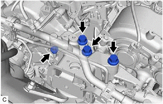
Remove the 3 bolts and nut and separate the engine mounting insulator sub-assembly RH from the front No. 1 engine mounting bracket LH.
-
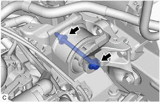
Remove the bolt and nut and separate the engine mounting insulator LH from the engine mounting bracket sub-assembly LH.
-
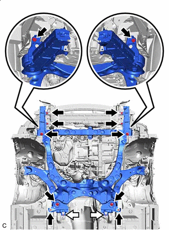

Bolt 
Nut Remove the 8 bolts and front bumper extension sub-assembly RH and front bumper extension sub-assembly LH from the front frame assembly and vehicle body.
-
Remove the 4 bolts, 2 nuts and front suspension member bracket sub-assembly RH and front suspension member bracket sub-assembly LH from the front frame assembly and vehicle body.
-
Operate the engine lifter and remove the engine assembly with transaxle from the vehicle.
Note
-
Make sure that the engine assembly with transaxle is clear of all wiring and hoses.
-
While lowering the engine assembly with transaxle from the vehicle, do not allow it to contact the vehicle.
-
-
-
DISCONNECT VACUUM HOSE
-
REMOVE STARTER ASSEMBLY
-
REMOVE BREATHER PLUG HOSE
-
DISCONNECT NO. 1 WATER BY-PASS HOSE
-
DISCONNECT WATER BY-PASS HOSE ASSEMBLY
-
REMOVE ENGINE WIRE
-
Disconnect all clamps and connectors and remove the engine wire from the engine assembly with transaxle.
-
-
INSTALL ENGINE HANGERS
-
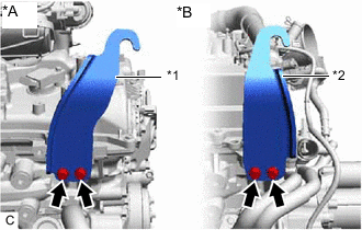
*A for Bank 1 *B for Bank 2 *1 No. 1 Engine Hanger *2 No. 2 Engine Hanger Install the No. 1 engine hanger and No. 2 engine hanger with the 4 bolts as shown in the illustration.
- Torque:
- 33 N*m { 337 kgf*cm, 24 ft.*lbf }
Tech Tips
No. 1 Engine Hanger 12281-31121 No. 2 Engine Hanger 12282-31100 Bolt 91671-10825 -
Using an engine sling device and engine lifter, secure the engine assembly with transaxle.
Note
-
Adjust the angle of the sling device carefully to prevent damage or deformation to the engine hangers or engine assembly.
-
Do not perform any procedures while the engine assembly is suspended because doing so may cause the engine assembly to drop, resulting in injury. However, the engine assembly needs to be suspended when it is installed to or removed from an engine stand.
-
-
-
REMOVE FRONT FRAME ASSEMBLY
-
Remove the bolt and separate the front engine mounting insulator from the front engine mounting bracket.
-
Remove the 4 nuts and separate the rear engine mounting insulator from the front frame assembly.
-
-
REMOVE FRONT ENGINE MOUNTING INSULATOR
Tech Tips
Perform this procedure only when replacement of the front engine mounting insulator is necessary.
-
Remove the 3 nuts and front engine mounting insulator from the front frame assembly.
-
-
REMOVE REAR ENGINE MOUNTING INSULATOR
Tech Tips
Perform this procedure only when replacement of the rear engine mounting insulator is necessary.
-
REMOVE FRONT ENGINE MOUNTING BRACKET
-
REMOVE AUTOMATIC TRANSAXLE ASSEMBLY
-
REMOVE DRIVE PLATE AND RING GEAR SUB-ASSEMBLY
-
REMOVE NO. 1 CRANKSHAFT POSITION SENSOR PLATE
-
INSTALL ENGINE ASSEMBLY TO ENGINE STAND
-
Install the engine assembly to an engine stand.
-
-
REMOVE ENGINE HANGERS
-
Remove the 4 bolts, No. 1 engine hanger and No. 2 engine hanger from the cylinder head sub-assembly and cylinder head LH.
-
-
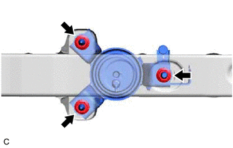
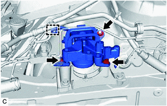
REMOVE ENGINE MOUNTING INSULATOR SUB-ASSEMBLY RH
Tech Tips
Perform this procedure only when replacement of the engine mounting insulator sub-assembly RH is necessary.
-
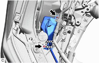
Disengage the clamp.
-
Remove the bolt, nut and separate the radiator reserve tank assembly.
-
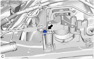
Remove the bolt and separate the bracket from the engine mounting insulator sub-assembly RH.
-
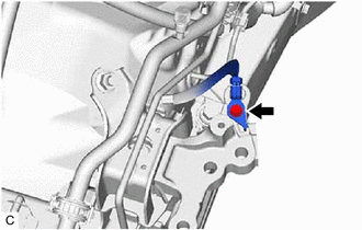
Remove the bolt and disconnect the No. 1 bond cable from the engine mounting insulator sub-assembly RH.
-
Disengage the clamp.
-
Remove the nut, 2 bolts and engine mounting insulator sub-assembly RH from the engine mounting spacer and vehicle body.
-
-
REMOVE ENGINE MOUNTING SPACER
Tech Tips
Perform this procedure only when replacement of the engine mounting spacer is necessary.
-
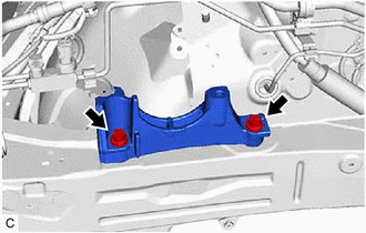
Remove the 2 bolts and engine mounting spacer from the vehicle body.
-
-
REMOVE ENGINE MOUNTING BRACKET SUB-ASSEMBLY LH
Tech Tips
Perform this procedure only when replacement of the engine mounting bracket sub-assembly LH is necessary.
-
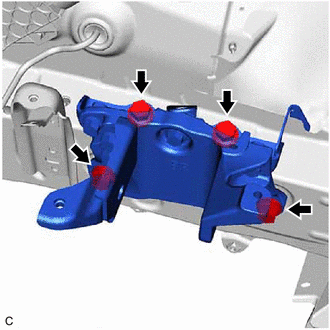
Remove the 4 bolts and engine mounting bracket sub-assembly LH from the vehicle body.
-
-
REMOVE ENGINE MOUNTING INSULATOR LH
Tech Tips
Perform this procedure only when replacement of the engine mounting insulator LH is necessary.