METER / GAUGE SYSTEM Tachometer Malfunction
| DTC Code | DTC Name |
|---|---|
| Tachometer Malfunction |
DESCRIPTION
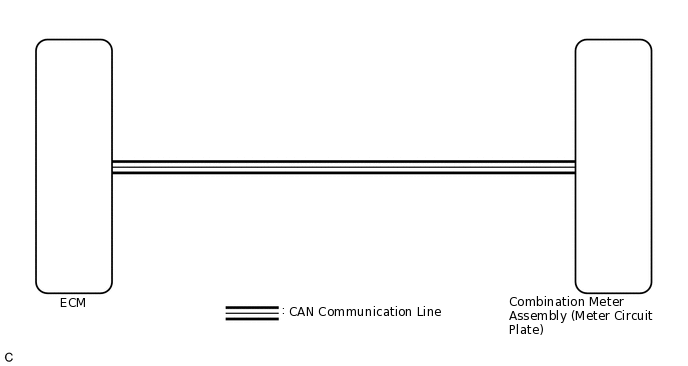
In this circuit, the combination meter assembly receives engine speed signals from the ECM using the CAN communication system. The combination meter assembly displays the engine speed calculated based on the data received from the ECM.
WIRING DIAGRAM
PROCEDURE
CHECK CAN COMMUNICATION SYSTEM
Check if CAN communication DTCs are output.
Result
Result
Proceed to
CAN communication DTCs are not output.
A
CAN communication DTCs are output.
B
PERFORM ACTIVE TEST USING GTS (TACHOMETER OPERATION)
Connect the GTS to the DLC3.
Turn the ignition switch to ON.
Turn the GTS on.
Enter the following menus: Body Electrical / Combination Meter / Active Test.
Check the operation by referring to the table below.
Body Electrical > Combination Meter > Active Test
Tester Display
Measurement Item
Control Range
Diagnostic Note
TachoMeter Operation
Tachometer
OFF, 0, 1000, 2000, 3000, 4000, 5000, 6000*, 7000*
-
*: for Gasoline
Body Electrical > Combination Meter > Active Test
Tester Display
TachoMeter Operation
OK
Tachometer indication is normal.
Result
Proceed to
OK
NG
READ VALUE USING GTS (ENGINE RPM)
Connect the GTS to the DLC3.
Turn the ignition switch to ON.
Turn the GTS on.
Enter the following menus: Body Electrical / Combination Meter / Data List.
Check the values by referring to the table below.
Body Electrical > Combination Meter > Data List
Tester Display
Measurement Item
Range
Normal Condition
Diagnostic Note
Engine Rpm
Engine speed
Min.: 0 rpm, Max.: 12750 rpm
1NR-FE:
600 to 700 rpm (Idling)
1ZR-FAE:
600 to 700 rpm (Idling (for CVT))
580 to 680 rpm (Idling (for Multi-mode manual transaxle))
1AD-FTV:
720 to 820 rpm (Idling)
1ND-TV:
720 to 820 rpm (Idling)
-
Body Electrical > Combination Meter > Data List
Tester Display
Engine Rpm
OK
Engine speed displayed on the GTS is almost the same as the tachometer indication.
Tip:When the Data List values and tachometer values match, a signal output error of the ECM or an internal malfunction of the combination meter assembly is suspected.
When the Data List values and tachometer values do not match, an internal malfunction of the combination meter assembly is suspected.
Result
Proceed to
OK
NG
CHECK FOR DTC
Check if SFI system or ECD system DTCs are output.
SFI system for 1NR-FE:Click here
SFI system for 1ZR-FAE:Click here
ECD system for 1ND-TV:Click here
ECD system for 1AD-FTV:Click here
Result
Result
Proceed to
DTCs are not output.
A
DTCs are output (for SFI system).
B
DTCs are output (for ECD system).
C
READ VALUE USING GTS (ENGINE SPEED, ENGINE RPM)
Connect the GTS to the DLC3.
Turn the ignition switch to ON.
Turn the GTS on.
Enter the following menus:
for Engine and ECT: Powertrain / Engine and ECT / Data List.
for Combination Meter: Body Electrical / Combination Meter / Data List.
Check the values by referring to the table below.
Engine and ECT (for Gasoline)
Powertrain > Engine and ECT > Data List
Tester Display
Measurement Item
Range
Normal Condition
Reference Value
Diagnostic Note
Engine Speed
Engine speed
Min.: 0 rpm, Max.: 16383 rpm
1NR-FE:
600 to 700 rpm (Idling)
1ZR-FAE:
600 to 700 rpm (Idling (for CVT))
580 to 680 rpm: Idling (for Manual transaxle)
1NR-FE:
-
1ZR-FAE:
666 rpm (Idling (engine warmed up and A/C off))
Stored as Freeze Frame Data: Yes
When the crankshaft position sensor is malfunctioning, "Engine Speed" is approximately 0 rpm or varies greatly from the actual engine speed.
Powertrain > Engine and ECT > Data List
Tester Display
Engine Speed
Engine and ECT (for Diesel)
Powertrain > Engine and ECT > Data List
Tester Display
Measurement Item
Type
Range
Normal Condition
Reference Value
Diagnostic Note
Engine Speed
Engine speed
Sensor output (crankshaft position sensor)
Min.: 0 rpm, Max.: 16383 rpm
1AD-FTV:
50 to 400 rpm (Cranking)
720 to 820 rpm (Idling with warm engine)
1ND-TV:
720 to 820 rpm (Idling)
1AD-FTV:
-
1ND-TV:
770 rpm (Idling ("Coolant Temp" = 75°C (167°F)))
When the crankshaft position sensor is malfunctioning, "Engine Speed" is approximately 0 or varies greatly from the actual engine speed.
Cause of out of range:
Crankshaft position sensor
Crankshaft position sensor circuit
Powertrain > Engine and ECT > Data List
Tester Display
Engine Speed
Combination Meter
Body Electrical > Combination Meter > Data List
Tester Display
Measurement Item
Range
Normal Condition
Diagnostic Note
Engine Rpm
Engine speed
Min.: 0 rpm, Max.: 12750 rpm
1NR-FE:
600 to 700 rpm: Idling
1ZR-FAE:
600 to 700 rpm: Idling (for CVT)
manual transaxle)
1AD-FTV:
720 to 820 rpm: Idling
1ND-TV:
720 to 820 rpm: Idling
-
Body Electrical > Combination Meter > Data List
Tester Display
Engine Rpm
Result
Result
Proceed to
The data list values of the ECUs do not match.
A
The data list values of the ECUs match
B
Tip:When the Data List values of the ECUs match, an internal malfunction of the ECM is suspected.
When the Data List values of the ECUs do not match, a signal output error of the ECM or an internal malfunction of the combination meter assembly is suspected.
B REPLACE ECM
REPLACE COMBINATION METER ASSEMBLY
Replace the combination meter assembly with a new or known good one.
OK
The operation of the tachometer returns to normal.
Result
Proceed to
OK
NG
OK END
NG REPLACE ECM