ENGINE UNIT
-
CONSTRUCTION
-
A 4-blade vane type VVT-i controller (camshaft timing exhaust gear assembly) is used on the exhaust side.
-
When the engine is stopped, a lock pin locks the exhaust camshaft at the most advanced position in order to enhance startability.
-
An advance assist spring is provided in the VVT-i controller (camshaft timing exhaust gear assembly) to assist the necessary torque in the advanced direction to keep the lock pin securely connected when the engine is stopped.
-
The ECM controls the amount of oil pressure applied to the advanced chamber and retarded chamber inside the VVT-i controller (camshaft timing exhaust gear assembly) based on signals from each sensor via the camshaft timing oil control valve assembly installed on the cylinder head cover sub-assembly and continuously changes the exhaust camshaft (No. 2 camshaft) phase.
Figure 1. VVT-i Controller (Camshaft Timing Exhaust Gear Assembly)
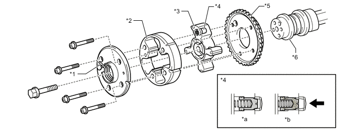
*1 Advance Assist Spring *2 Housing *3 Vane (Fixed on Exhaust Camshaft (No. 2 Camshaft)) *4 Lock Pin *5 Sprocket *6 Exhaust Camshaft (No. 2 Camshaft) *a Engine Stopped *b Engine Running 
Oil Pressure - -
-
-
OPERATION
-
Advance
-
When the camshaft timing oil control valve assembly is positioned as shown in the illustration by the advance signal from the ECM, oil pressure is applied to the advance side vane chamber to rotate the exhaust camshaft (No. 2 camshaft) in the advance direction.
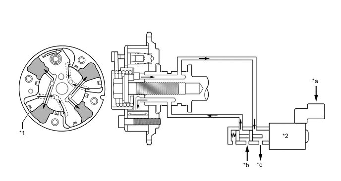
*1 Vane *2 Camshaft Timing Oil Control Valve Assembly *a From ECM *b Oil Pressure *c Drain - - 
Rotation Direction - -
-
-
Retard
-
When the camshaft timing oil control valve assembly is positioned as shown in the illustration by the retard signals from the ECM, oil pressure is applied to the retard side vane chamber to rotate the exhaust camshaft (No. 2 camshaft) in the retard direction.
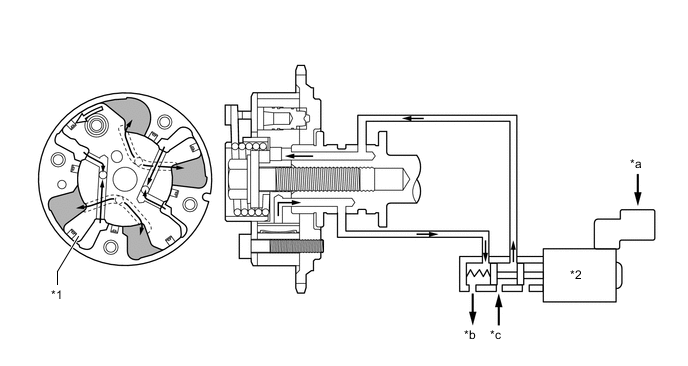
*1 Vane *2 Camshaft Timing Oil Control Valve Assembly *a From ECM *b Drain *c Oil Pressure - - Rotation Direction - -
-
-
Hold
-
The ECM calculates the target advanced angle according to driving conditions and performs control. After setting to the target timing, timings are maintained by the neutral camshaft timing oil control valve assembly as long as driving conditions do not change. As a result, unnecessary engine oil discharge is suppressed while valve timings are set to the desired target position.
-
-