METER / GAUGE SYSTEM Hybrid System Indicator Malfunction
| DTC Code | DTC Name |
|---|---|
| Hybrid System Indicator Malfunction |
DESCRIPTION
A hybrid system indicator has been used on this vehicle. In this circuit, the combination meter assembly receives the eco-zone indicator level signal from the hybrid vehicle control ECU via CAN communication. The combination meter assembly controls the operation of the hybrid system indicator according to the eco-zone indicator level signal received from the hybrid vehicle control ECU via CAN communication.
WIRING DIAGRAM
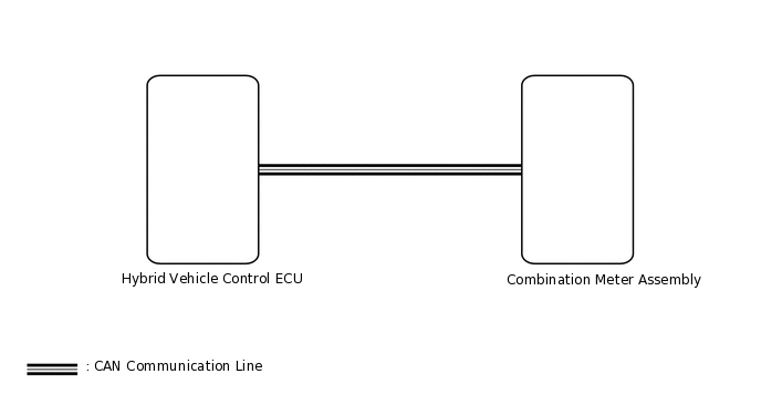
CAUTION / NOTICE / HINT
When replacing the combination meter assembly, make sure to replace it with a new one.
PROCEDURE
CHECK FOR DTC (CAN COMMUNICATION SYSTEM)
Check for DTCs.
OK
No DTCs are output.
Result
Proceed to
OK
NG
PERFORM ACTIVE TEST USING GTS (HV SYSTEM INDICATOR)
Using the GTS, perform the Active Test.
Body Electrical > Combination Meter > Active Test
Tester Display
Measurement Item
Control Range
Diagnostic Note
HV System Indicator
Hybrid system indicator
OFF, MIN, -50, 0, 100, 200, 300, 400, MAX
-
Body Electrical > Combination Meter > Active Test
Tester Display
HV System Indicator
OK
Hybrid system indicator indication is normal.
Result
Proceed to
OK
NG
READ VALUE USING GTS (HV SYSTEM INDICATOR)
Using the GTS, read the Data List.
Body Electrical > Combination Meter > Data List
Tester Display
Measurement Item
Range
Normal Condition
Diagnostic Note
HV System Indicator
Hybrid system indicator value
Min.: -512%, Max.: 511%
-512 to 511%
-
Body Electrical > Combination Meter > Data List
Tester Display
HV System Indicator
OK
Hybrid system indicator value displayed on the GTS is almost the same as hybrid system indicator indication.
Result
Proceed to
OK
NG
CHECK COMBINATION METER ASSEMBLY
Replace the combination meter assembly.
Check that the operation of the hybrid system indicator returns to normal.
OK
The operation of the hybrid system indicator returns to normal.
Result
Proceed to
OK
NG
OK END (COMBINATION METER ASSEMBLY IS DEFECTIVE)