AIR CONDITIONING SYSTEM(except Automatic Air Conditioning System) SYSTEM DESCRIPTION
GENERAL
The air conditioning system has the following controls.
Control
Outline
Manual Control
Damper positions and blower speed are adjusted automatically according to the operation of switches such as the temperature control switch, blower switch, mode control switch and inlet control switch.
Compressor Control
Through the calculation of the target evaporator temperature based on various sensor signals, the air conditioning control optimally controls discharge capacity by regulating the opening extent of the compressor solenoid valve.
Mode Position and Damper Operation
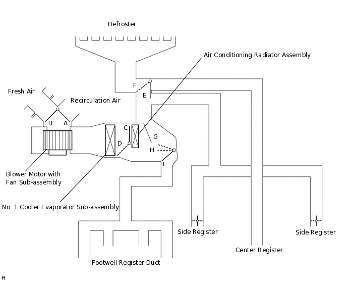
Table 1. Functions of Main Dampers Control Damper
Operation Position
Damper Position
Operation
Air Inlet Control Damper
FRESH
A
Allows fresh air to enter.
RECIRCULATION
B
Causes air inside the cabin to be recirculated.
Air Mix Control Damper
MAX COLD to MAX HOT Temperature Setting
C - D
Varies the mixture ratio of warm air and cool air in order to regulate the temperature continuously between hot and cold.
Air Outlet Control Damper
DEF

E, I
Air blows out of the defroster and side registers.
FOOT / DEF

E, H
Air blows out of the footwell register ducts, side registers and defroster.
FOOT

E, G
Air blows out of the footwell register ducts. Additionally, air blows out slightly from the defroster and side registers.
BI-LEVEL

F, H
Air blows out of the footwell register ducts, center register and side registers.
FACE

F, I
Air blows out of the center register and side registers.
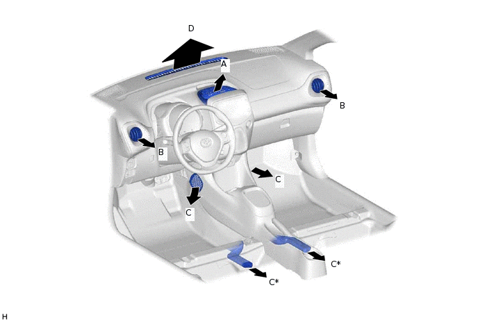
AIR OUTLETS AND AIRFLOW VOLUME
Air Outlets and Airflow Volume.
*
w/ Rear Air Duct
-
-
Mode
FACE
FOOT
DEF
Center
Side
C
D
A
B
FACE


BI-LEVEL
FOOT
FOOT / DEF
DEF
The size of each circle ○ indicates the ratio of airflow volume.
COMPRESSOR (w/ Cooler System)
A rotary vane type compressor with magnet clutch is used.
NO. 1 COOLER THERMISTOR (w/ Cooler System)
The No. 1 cooler thermistor detects the temperature of the cool air immediately after the evaporator in the form of resistance changes, and outputs it to the air conditioning control assembly.
BLOWER MOTOR
The blower motor with fan sub-assembly has a built-in blower controller, and is controlled using duty control performed by the air conditioning control assembly.
BLOWER RESISTOR
The blower resistor controls the blower motor with fan sub-assembly based on changes in the signal sent by the air conditioning control assembly.
THERMISTOR ASSEMBLY
The thermistor assembly detects the outside temperature based on changes in the resistance of its built-in thermistor and sends a signal to the combination meter assembly.
PRESSURE SWITCH (w/ Cooler System)
When a refrigerant pressure malfunction is detected, the pressure switch suspends A/C on signals sent from the air conditioning control assembly to the ECM and cuts the current to the magnet clutch to stop the compressor.