CLUTCH SYSTEM DETAILS CLUTCH COVER
CONSTRUCTION
LCC (Load Controlled Clutch Cover) Mechanism (Models with C553A Multi-mode Manual Transaxle)
To minimize the increase in the clutch operating load that results from the change in the pressure plate height with the wear of the clutch disc facing, the LCC (Load Controlled Clutch cover) mechanism mechanically adjusts the pressure plate height to a predetermined position.
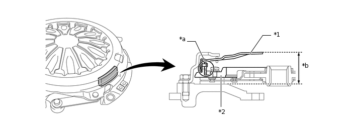
*1
Diaphragm Spring
*2
Lower Pressure Plate
*a
LCC Mechanism
*b
Adjust Ring
The LCC mechanism is provided in the clutch cover and consists of a pinion, which is located on the upper pressure plate, and a lower rack, upper rack, adjustment wedge, and spring, which are located on the lower pressure plate.
Upon determining an increase in the clutch operating load due to an increase in amperage through the clutch motor, the M-MT ECU operates the clutch actuator in order to move the diaphragm spring to the operating range of the LCC mechanism. This enables the LCC mechanism to operate and mechanically adjust the pressure plate height to a predetermined position.
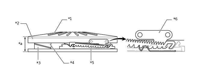
*1
Diaphragm Spring
*2
Upper Pressure Plate
*3
Lower Pressure Plate
*4
Adjustment Wedge
*5
Lower Rack
*6
Pinion
*a
LCC Mechanism
-
-
OPERATION
LCC (Load Controlled Clutch Cover) Mechanism (Models with C553A Multi-mode Manual Transaxle)
Tip:If the M-MT ECU determines that the clutch operating load is more than normal based on the clutch motor amperage, it activates the clutch actuator to operate the LCC mechanism after the ignition switch is turned off with the vehicle stopped. The M-MT ECU starts this operation prior to the parking control that is performed when the ignition switch is turned off.
The diaphragm spring is compressed to the LCC operation range by the clutch actuator, allowing the upper pressure plate and the pinion to move upward more than normal. As a result, the pinion and upper rack become disengaged.
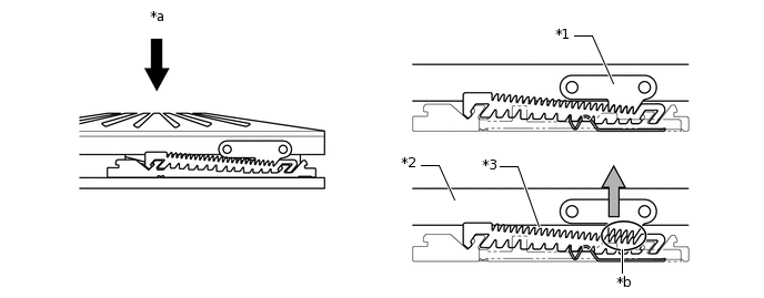
*1
Pinion
*2
Upper Pressure Plate
*3
Upper Rack
-
-
*a
Compression Force
*b
Disengage
When the pinion and upper rack are disengaged, the spring force causes the upper rack to move along the teeth of the lower rack. As a result, the tooth position of the upper rack and pinion shifts by 1 pitch.

*1
Spring
-
-
*a
Spring Force
-
-
The M-MT ECU stops the clutch actuator based on signals from the clutch stroke sensor. As a result, the pinion and the upper pressure plate engage with the lower rack in the new tooth position.
As the upper plate moves along the teeth of the lower rack, it is pushed farther from the lower rack by the adjustment wedge. This changes the position of the diaphragm spring, thus adjusting the required operation force.

*a
1 Pitch
-
-
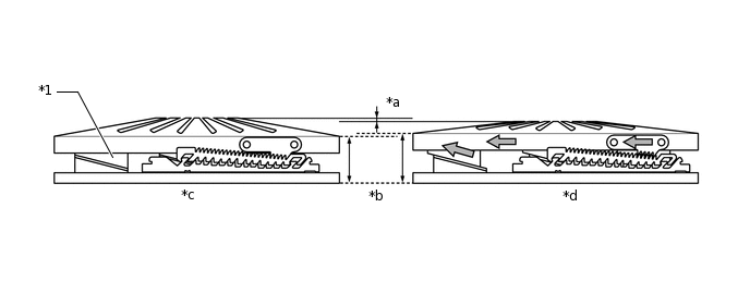
*1
Adjustment Wedge
-
-
*a
Diaphragm Spring Height
*b
Upper Pressure Plate Height
*c
Before load control operation
*d
After load control operation
Tip:Diaphragm Spring Height: Height Before > Height After
Upper Pressure Plate Height: Height Before < Height After