ECD SYSTEM(w/ Glow Plug Controller), Diagnostic DTC:P0522 and P0523
| DTC Code | DTC Name |
|---|---|
| P0522 | Engine Oil Pressure Sensor / Switch Low |
| P0523 | Engine Oil Pressure Sensor / Switch High |
DESCRIPTION
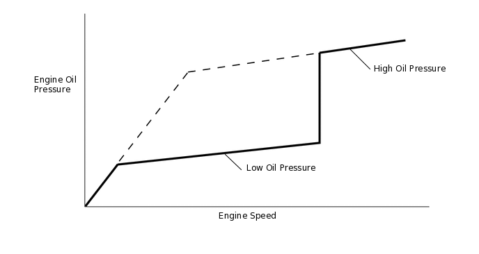
The oil pressure control system reduces and increases engine oil pressure using the oil pressure switching valve in the timing chain cover assembly. When the engine speed reaches 2600 rpm while racing the engine after warming it up, the oil pressure switching valve operates and the engine oil pressure system changes from low pressure control mode to high pressure control mode. When the engine speed drops to 2400 rpm, the engine oil pressure system changes from high pressure control mode to low pressure control mode*. The oil pressure sender gauge assembly detects the engine oil pressure.
*: If the oil temperature is presumed high, the high pressure control mode is used at all engine speeds.
DTC No. |
Detection Item |
DTC Detection Condition |
Trouble Area |
MIL |
Memory |
|---|---|---|---|---|---|
P0522 |
Engine Oil Pressure Sensor / Switch Low |
Oil pressure sender gauge assembly output voltage is 0.04 V or less. (2 trip detection logic) |
|
Comes on |
DTC stored |
P0523 |
Engine Oil Pressure Sensor / Switch High |
Oil pressure sender gauge assembly output voltage is 4.7 V or higher. (2 trip detection logic) |
|
Comes on |
DTC stored |
DTC No. |
DTC Detection Drive Pattern |
|---|---|
P0522 P0523 |
Ignition switch ON for 4 seconds |
DTC No. |
DTC Detection Drive Pattern |
|---|---|
P0522 P0523 |
Engine Oil Pressure |
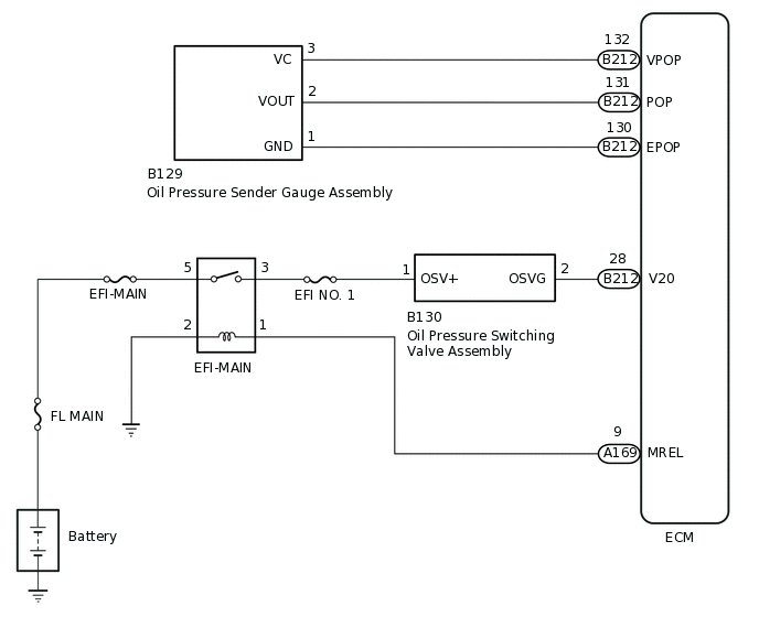
WIRING DIAGRAM
CAUTION / NOTICE / HINT
When replacing the ECM, perform ECM Initialization and Registration.
Inspect the fuses for circuits related to this system before performing the following procedure.
When the ECM must be replaced, before replacing the ECM, perform the "Learning Values Save" function using the GTS. Then after installing a new ECM, perform all of the initialization and registration procedures for the "Learning Values Write" function by following the instructions shown on the GTS display.
Read freeze frame data using the GTS. Freeze frame data records the engine condition when malfunctions are detected. When troubleshooting, freeze frame data can help determine if the vehicle was moving or stationary, if the engine was warmed up or not, and other data from the time the malfunction occurred.
PROCEDURE
CHECK HARNESS AND CONNECTOR (OIL PRESSURE SENDER GAUGE ASSEMBLY - ECM)
Disconnect the oil pressure sender gauge assembly connector.
Disconnect the ECM connector.
Measure the resistance according to the value(s) in the table below.
Standard Resistance
Tester Connection
Condition
Specified Condition
B129-3 (VC) - B212-132 (VPOP)
Always
Below 1 Ω
B129-2 (VOUT) - B212-131 (POP)
Always
Below 1 Ω
B129-1 (GND) - 212-130 (EPOP)
Always
Below 1 Ω
B129-3 (VC) or B212-132 (VPOP) - Body ground and other terminals
Always
10 kΩ or higher
B129-2 (VOUT) or B212-131 (POP) - Body ground and other terminals
Always
10 kΩ or higher
B129-1 (GND) or B212-130 (EPOP) - Body ground and other terminals
Always
10 kΩ or higher
Result
Proceed to
OK
NG
NG REPAIR OR REPLACE HARNESS OR CONNECTORClick here
CHECK TERMINAL VOLTAGE (VC VOLTAGE)
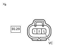
*a
Front view of wire harness connector
(to Oil Pressure Sender Gauge Assembly)
Disconnect the oil pressure sender gauge assembly connector.
Turn the ignition switch to ON.
Measure the voltage according to the value(s) in the table below.
Standard Voltage
Tester Connection
Condition
Specified Condition
B129-3 (VC) - Body ground
Ignition switch ON
4.75 to 5.25 V
Result
Proceed to
OK
NG
NG REPLACE ECMClick here
REPLACE OIL PRESSURE SENDER GAUGE ASSEMBLY
Replace the oil pressure sender gauge assembly.
Result
Proceed to
NEXT
CHECK WHETHER DTC OUTPUT RECURS (P0522 AND/OR P0523)
Connect the GTS to the DLC3.
Turn the ignition switch to ON and turn the GTS on.
Clear the DTCs.
Powertrain > Engine and ECT > Clear DTCs
Turn the ignition switch off and wait for 30 seconds or more.
Turn the ignition switch to ON and wait for 4 seconds or more.
Enter the following menus: Powertrain / Engine and ECT / Trouble Codes / Pending.
Read the pending DTCs.
Powertrain > Engine and ECT > Trouble Codes
Result
Result
Proceed to
DTC P0522 and/or P0523 is output
A
DTC is not output
B
B END
REPLACE ECM
Replace the ECM.
Result
Proceed to
NEXT
NEXT CONFIRM WHETHER MALFUNCTION HAS BEEN SUCCESSFULLY REPAIREDClick here
REPAIR OR REPLACE HARNESS OR CONNECTOR
Result
Proceed to
NEXT
CONFIRM WHETHER MALFUNCTION HAS BEEN SUCCESSFULLY REPAIRED
Connect the GTS to the DLC3.
Turn the ignition switch to ON and turn the GTS on.
Clear the DTCs.
Powertrain > Engine and ECT > Clear DTCs
Turn the ignition switch off and wait for 30 seconds or more.
Turn the ignition switch to ON and wait for 4 seconds or more.
Enter the following menus: Powertrain / Engine and ECT / Trouble Codes / Pending.
Confirm that the pending DTC is not output again.
Powertrain > Engine and ECT > Trouble Codes
Result
Proceed to
NEXT
NEXT END