POWER BACK DOOR SYSTEM TERMINALS OF ECU
-
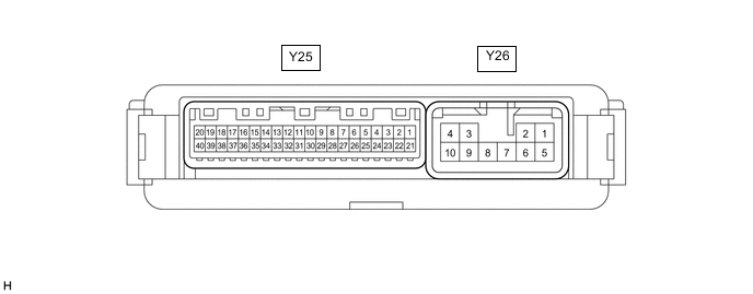
CHECK MULTIPLEX NETWORK DOOR ECU
-
Disconnect the Y25 and Y26 multiplex network door ECU connectors.
-
Measure the voltage and resistance according to the value(s) in the table below.
Terminal No. (Symbol) Wiring Color Terminal Description Condition Specified Condition Y25-18 (IG) - Body ground W - Body ground IG power supply Engine switch on (IG) 11 to 14 V Engine switch off Below 1 V Y25-20 (ECUB) - Body ground W - Body ground Battery power supply Always 11 to 14 V Y26-1 (B) - Body ground LA-W - Body ground Battery power supply Always 11 to 14 V Y26-10 (GND) - Body ground W-B - Body ground Body ground Always Below 1 Ω -
Reconnect the Y25 and Y26 multiplex network door ECU connectors.
-
Measure the voltage and waveform according to the value(s) in the table below.
Terminal No. (Symbol) Wiring Color Terminal Description Condition Specified Condition Y25-1 (DS1) - Body ground L - Body ground Power back door unit assembly LH (door sensor) signal Power back door not operating 7 V or higher Power back door operating Pulse generation
(See waveform 1)
Y25-2 (DS2) - Body ground R - Body ground Power back door unit assembly LH (door sensor) signal Power back door not operating 7 V or higher Power back door operating Pulse generation
(See waveform 2)
Y25-3 (DS12) - Body ground LG - Body ground Power back door unit assembly RH (door sensor) signal Power back door not operating 7 V or higher Power back door operating Pulse generation
(See waveform 1)
Y25-4 (DS22) - Body ground B - Body ground Power back door unit assembly RH (door sensor) signal Power back door not operating 7 V or higher Power back door operating Pulse generation
(See waveform 2)
Y25-5 (DSV2) - Body ground BE - Body ground Power back door unit assembly RH (door sensor) power supply Always 7 V or higher Y25-6 (OSR) - Y25-24 (OSE) SB - GR Power back door sensor assembly RH signal Power back door sensor assembly RH not pressed 4 to 6 V Power back door sensor assembly RH pressed Below 1 V Y25-8 (BDDN) - Body ground LG - Body ground Back door control switch signal Back door control switch on Below 1 V Back door control switch off Pulse generation Y25-10 (CLSW) - Body ground V - Body ground Door control switch signal Door control switch on Below 1 V Door control switch off 11 to 14 V Y25-14 (KSIN) - Body ground* W - Body ground Kick detection signal Kick door control sensor not detecting a foot → detecting a foot Pulse generation
(See waveform 3)
Y25-16 (BZR+) - Body ground V - Body ground Wireless door lock buzzer signal Power back door warning buzzer sounding Pulse generation Power back door warning buzzer not sounding Below 1 V Y25-19 (DSG2) - Body ground V - Body ground Power back door unit assembly RH (door sensor) ground Always Below 1 V Y25-21 (DSG) - Body ground GR - Body ground Power back door unit assembly LH (door sensor) ground Always Below 1 V Y25-25 (DSV) - Body ground G - Body ground Power back door unit assembly LH (door sensor) power supply Always 7 V or higher Y25-26 (OSL) - Y25-24 (OSE) P - GR Power back door sensor assembly LH signal Power back door sensor assembly LH not pressed 4 to 6 V Power back door sensor assembly LH pressed Below 1 V Y26-4 (DC+) - Y26-3 (DC-) LA-BR - LA-R Back door lock assembly (back door lock motor) circuit Back door lock motor operating 11 to 14 V Back door lock motor not operating Below 1 V *: w/ Hands Free Power Back Door
-

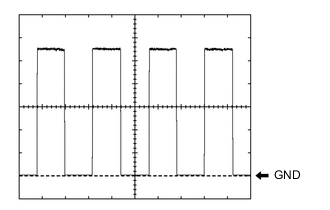
Using an oscilloscope, check waveform 1.
Waveform 1 (Reference) Item Condition Tester Connection
-
Y25-1 (DS1) - Body ground
-
Y25-3 (DS12) - Body ground
Tool setting 2 V/DIV., 2 ms./DIV. Vehicle condition Power back door operating Tech Tips
The period changes in accordance to the speed at which the power back door is opened and closed.
-
-
Using an oscilloscope, check waveform 2.
Waveform 2 (Reference) Item Condition Tester Connection
-
Y25-2 (DS2) - Body ground
-
Y25-4 (DS22) - Body ground
Tool setting 2 V/DIV., 2 ms./DIV. Vehicle condition Power back door operating Tech Tips
The period changes in accordance to the speed at which the power back door is opened and closed.
-
-
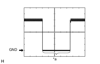
*a Kick detection signal Using an oscilloscope, check waveform 3.
Waveform 3 (Reference) Item Content Tester connection Y26-14 (KSIN) - Body ground Tool setting 2 V/DIV., 50 ms./DIV. Vehicle condition Kick door control sensor not detecting a foot → detecting a foot
-
-
-
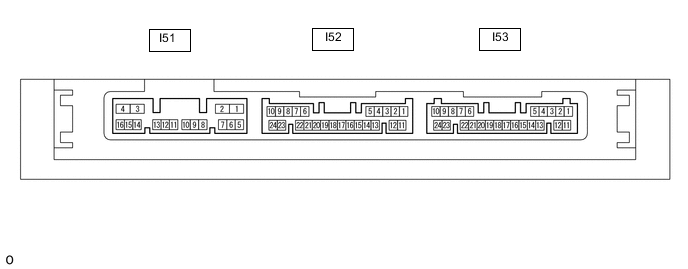
CHECK CERTIFICATION ECU (SMART KEY ECU ASSEMBLY)
-
Disconnect the I53 certification ECU (smart key ECU assembly) connector.
-
Measure the voltage and resistance according to the value(s) in the table below.
Terminal No. (Symbol) Wiring Color Terminal Description Condition Specified Condition I53-10 (+B) - Body ground W - Body ground Battery power supply Always 11 to 14 V I53-11 (E) - Body ground W-B - Body ground Body ground Always Below 1 Ω -
Reconnect the I53 certification ECU (smart key ECU assembly) connector.
-
Measure the waveform according to the value(s) in the table below.
Terminal No. (Symbol) Wiring Color Terminal Description Condition Specified Condition I52-5 (TSW5) - Body ground Y - Body ground Back door opener switch assembly signal Back door opener switch assembly (open switch) off → on Pulse generation (See waveform 1)
-
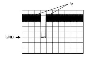
*a In actuality, sampling is being performed Using an oscilloscope, check waveform 1.
Waveform 1 (Reference) Item Content Terminal No. (Symbol) I52-5 (TSW5) - I53-11 (E) Tool Setting 2 V/DIV., 500 ms./DIV. Condition Back door opener switch assembly (open switch) off → on
-
-
-
CHECK MAIN BODY ECU (MULTIPLEX NETWORK BODY ECU) AND INSTRUMENT PANEL JUNCTION BLOCK ASSEMBLY
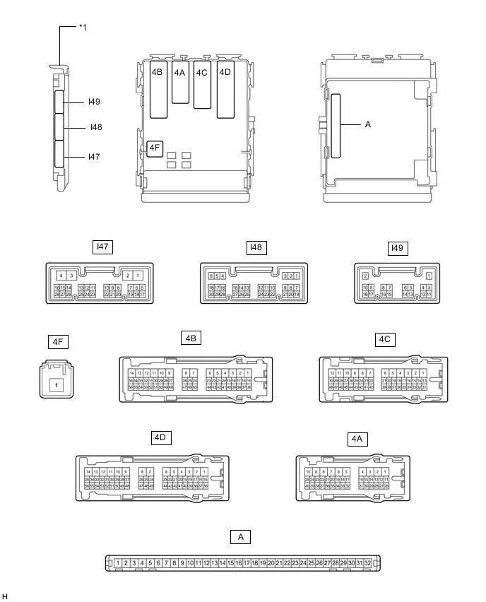
*1 Main Body ECU (Multiplex Network Body ECU) - -
-
Remove the main body ECU (multiplex network body ECU).
for LHD : Click here
for RHD : Click here
-
Connect the instrument panel junction block assembly connectors.
-
Measure the voltage and resistance according to the value(s) in the table below.
Terminal No. (Symbol) Wiring Color Terminal Description Condition Specified Condition A-31 (BECU) - Body ground None - Body ground Battery power supply Always 11 to 14 V A-30 (ACC) - Body ground None - Body ground ACC power supply Engine switch on (ACC) 11 to 14 V Engine switch off Below 1 V A-32 (IG) - Body ground None - Body ground IG power supply Engine switch on (IG) 11 to 14 V Engine switch off Below 1 V A-11 (GND1) - Body ground None - Body ground Body ground Always Below 1 Ω -
Install the main body ECU (multiplex network body ECU).
for LHD : Click here
for RHD : Click here
-
Measure the voltage and waveform according to the value(s) in the table below.
Terminal No. (Symbol) Wiring Color Terminal Description Condition Specified Condition I47-5 (PBDS) - Body ground R - Body ground Combination switch assembly signal Combination switch assembly off Pulse generation Combination switch assembly on Below 1 V
-