AIR CONDITIONING SYSTEM
-
CONSTRUCTION
-
An air conditioning unit that is compatible with left and right independent temperature control is used.
-
A partial recirculation structure that circulates a portion of the air in the cabin when in fresh air mode is used in an effort to improve heater performance
-
A Multi-Flow-IV (MF-IV) sub-cool type evaporator is used.
-
A Straight Flow Aluminum-II (SFA-II) heater core that is compact and offers advanced performance is used.
-
A pollen and odor-removing type clean air filter (air refiner element) is provided as standard equipment.
Figure 1. Air Conditioning Unit Layout Parts Location
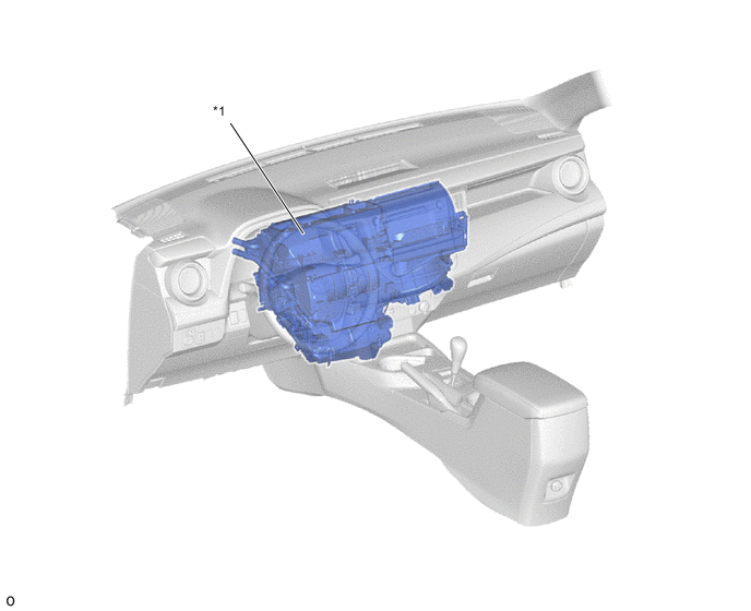
*1 Air Conditioning Unit Assembly - - Figure 2. Duct Layout Parts Location
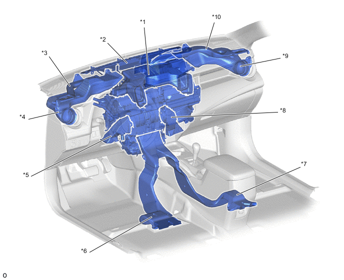
*1 Center Register Duct *2 Front Defroster Duct *3 Driver Side Defroster Duct *4 Driver Side Register Duct *5 Driver Side Footwell Register Duct *6 Driver Side Rear Footwell Register Duct *7 Front Passenger Side Rear Footwell Register Duct *8 Front Passenger Side Footwell Register Duct *9 Front Passenger Side Register Duct *10 Front Passenger Side Defroster Duct
-
-
OPERATION
-
Mode Position and Damper Operation
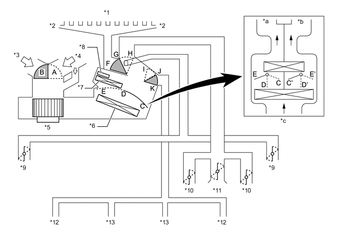
*1 Front Defroster *2 Side Defroster *3 Fresh Air *4 Recirculated Air *5 Blower with Fan Motor Sub-assembly *6 No. 1 Cooler Evaporator Sub-assembly *7 Heater Radiator Unit Sub-assembly *8 PTC Heater (Quick Heater Assembly) *9 Side Register *10 Center Register *11 Upper Register *12 Rear Footwell Register Duct *13 Footwell Register - - *a Driver Side *b Passenger Side *c Models with Automatic Air Conditioning System - - Control Damper Operation Position Damper Position Operation Air Inlet Control Damper FRESH A Brings in fresh air. RECIRC A Recirculates internal air. Air Mix Control Damper Temp. Setting: 16 °C (61 °F) to 32 °C (90 °F) C - D - E (C'- D' -E') Varies the mixture ratio of the fresh air and the recirculation air in order to regulate the temperature continuously from HOT to COLD. Mode Control Damper 
DEF H, K Defrosts the windshield through the front defroster and side register. 
FOOT / DEF H, J Defrosts the windshield through the front defroster and side register, while air is also blown out from the footwell register duct and rear footwell register duct. 
FOOT H, I Air blows out of the footwell register duct, rear footwell register duct and side register. In addition, air blows out slightly from the front defroster. 
BI-LEVEL F, I Air blows out of the center register, side register, footwell register duct and rear footwell register duct. 
FACE F, K Air blows out of the center register and side register. -
Air Outlets and Airflow Volume
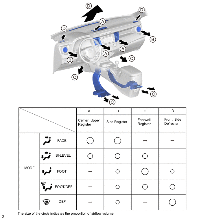
-