NAVIGATION SYSTEM, Diagnostic DTC:B15C3
| DTC Code | DTC Name |
|---|---|
| B15C3 | Speaker Output Short |
DESCRIPTION
This DTC is stored when a malfunction occurs in the speakers.
DTC No. |
Detection Item |
DTC Detection Condition |
Trouble Area |
|---|---|---|---|
B15C3 |
Speaker Output Short |
A short is detected in the speaker output circuit. |
|
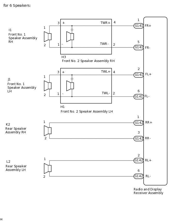
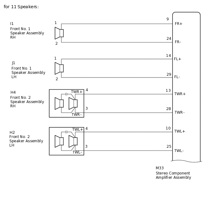
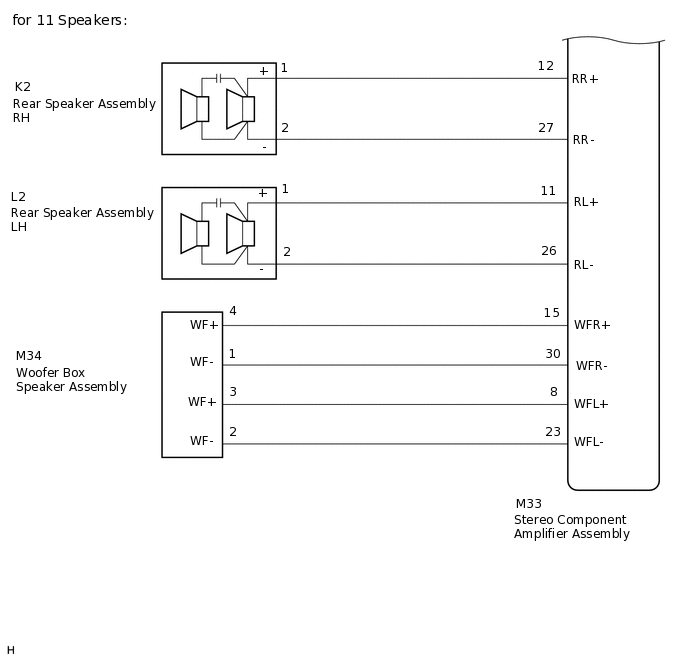
WIRING DIAGRAM
CAUTION / NOTICE / HINT
Check that the wire harness is properly installed and does not have any sharp bends, pinching or loose connections.
PROCEDURE
CHECK FOR DTC
Clear the DTCs.
Body Electrical > Navigation System > Clear DTCs
Check for DTCs.
Body Electrical > Navigation System > Trouble Codes
OK
No DTCs are output.
Result
Proceed to
OK
NG
CHECK VEHICLE CONDITION
Check the vehicle condition.
Result
Result
Proceed to
for 6 Speakers
A
for 11 Speakers
B
B CHECK HARNESS AND CONNECTOR (SPEAKER CIRCUIT)Click here
CHECK HARNESS AND CONNECTOR (SPEAKER CIRCUIT)
*1: for LH Side
*2: for RH Side
Disconnect the G141 and G142 radio and display receiver assembly connectors.
Disconnect the J1*1 and/or I1*2 front No. 1 speaker assembly connector.
Disconnect the H1*1 and/or H3*2 front No. 2 speaker assembly connector.
Disconnect the L2*1 and/or K2*2 rear speaker assembly connector.
Measure the resistance according to the value(s) in the table below.
Standard Resistance
Table 1. for LH Side Tester Connection
Condition
Specified Condition
G141-2 (FL+) - H1-4 (TWL+)
Always
Below 1 Ω
G141-6 (FL-) - H1-2 (TWL-)
Always
Below 1 Ω
H1-3 (+) - J1-1
Always
Below 1 Ω
H1-1 (-) - J1-2
Always
Below 1 Ω
G142-2 (RL+) - L2-1
Always
Below 1 Ω
G142-6 (RL-) - L2-2
Always
Below 1 Ω
G141-2 (FL+) - Body ground
Always
10 kΩ or higher
G141-6 (FL-) - Body ground
Always
10 kΩ or higher
G142-2 (RL+) - Body ground
Always
10 kΩ or higher
G142-6 (RL-) - Body ground
Always
10 kΩ or higher
H1-3 (+) - Body ground
Always
10 kΩ or higher
H1-1 (-) - Body ground
Always
10 kΩ or higher
Table 2. for RH Side Tester Connection
Condition
Specified Condition
G141-1 (FR+) - H3-4 (TWR+)
Always
Below 1 Ω
G141-5 (FR-) - H3-2 (TWR-)
Always
Below 1 Ω
H3-3 (+) - I1-1
Always
Below 1 Ω
H3-1 (-) - I1-2
Always
Below 1 Ω
G142-1 (RR+) - K2-1
Always
Below 1 Ω
G142-3 (RR-) - K2-2
Always
Below 1 Ω
G141-1 (FR+) - Body ground
Always
10 kΩ or higher
G141-5 (FR-) - Body ground
Always
10 kΩ or higher
G142-1 (RR+) - Body ground
Always
10 kΩ or higher
G142-3 (RR-) - Body ground
Always
10 kΩ or higher
H3-3 (+) - Body ground
Always
10 kΩ or higher
H3-1 (-) - Body ground
Always
10 kΩ or higher
Result
Proceed to
OK
NG
NG REPAIR OR REPLACE HARNESS OR CONNECTOR
INSPECT FRONT NO. 1 SPEAKER ASSEMBLY
Remove the front No. 1 speaker assembly connector.
Inspect the front No. 1 speaker assembly.
Result
Proceed to
OK
NG
CHECK FRONT NO. 2 SPEAKER ASSEMBLY
Replace the front No. 2 speaker assembly with a known good one.
Check the malfunction disappears.
Tip:Connect all the connectors to the front No. 2 speaker assemblies that were disconnected.
When there is a possibility that either the right or left front speaker is defective, inspect by interchanging the right one with the left one.
Perform the above inspection on both LH and RH sides.
OK
No DTCs are output.
Result
Proceed to
OK
NG
OK END (FRONT NO. 2 SPEAKER ASSEMBLY IS DEFECTIVE)
INSPECT REAR SPEAKER ASSEMBLY
Remove the rear speaker assembly connector.
Inspect the rear speaker assembly.
Result
Proceed to
OK
NG
CHECK HARNESS AND CONNECTOR (SPEAKER CIRCUIT)
*1: for LH Side
*2: for RH Side
Disconnect the M33 stereo component amplifier assembly connector.
Disconnect the J1*1 and/or I1*2 front No. 1 speaker assembly connector.
Disconnect the H2*1 and/or H4*2 front No. 2 speaker assembly connector.
Disconnect the L2*1 and/or K2*2 rear speaker assembly connector.
Disconnect the M34 Woofer box speaker assembly connector.
Measure the resistance according to the value(s) in the table below.
Standard Resistance
Table 3. for LH Side Tester Connection
Condition
Specified Condition
M33-14 (FL+) - J1-1
Always
Below 1 Ω
M33-29 (FL-) - J1-2
Always
Below 1 Ω
M33-10 (TWL+) - H2-4(TWL+)
Always
Below 1 Ω
M33-25 (TWL-) - H2-3(TWL-)
Always
Below 1 Ω
M33-11 (RL+) - L2-1(+)
Always
Below 1 Ω
M33-26 (RL-) - L2-2(-)
Always
Below 1 Ω
M33-14 (FL+) - Body ground
Always
10 kΩ or higher
M33-29 (FL-) - Body ground
Always
10 kΩ or higher
M33-10 (TWL+) - Body ground
Always
10 kΩ or higher
M33-25 (TWL-) - Body ground
Always
10 kΩ or higher
M33-11 (RL+) - Body ground
Always
10 kΩ or higher
M33-26 (RL-) - Body ground
Always
10 kΩ or higher
Table 4. for RH Side Tester Connection
Condition
Specified Condition
M33-9 (FR+) - I1-1
Always
Below 1 Ω
M33-24 (FR-) - I1-2
Always
Below 1 Ω
M33-13 (TWR+) - H4-4(TWR+)
Always
Below 1 Ω
M33-28 (TWR-) - H4-3(TWR-)
Always
Below 1 Ω
M33-12 (RR+) - K2-1(+)
Always
Below 1 Ω
M33-27 (RR-) - K2-2(-)
Always
Below 1 Ω
M33-9 (FR+) - Body ground
Always
10 kΩ or higher
M33-24 (FR-) - Body ground
Always
10 kΩ or higher
M33-13 (TWR+) - Body ground
Always
10 kΩ or higher
M33-28 (TWR-) - Body ground
Always
10 kΩ or higher
M33-12 (RR+) - Body ground
Always
10 kΩ or higher
M33-27 (RR-) - Body ground
Always
10 kΩ or higher
Table 5. for Woofer Box Speaker Tester Connection
Condition
Specified Condition
M33-15 (WFR+) - M34-4 (WF+)
Always
Below 1 Ω
M33-30 (WFR-) - M34-1 (WF-)
Always
Below 1 Ω
M33-8 (WFL+) - M34-3 (WF+)
Always
Below 1 Ω
M33-23 (WFL-) - M34-2 (WF-)
Always
Below 1 Ω
M33-15 (WFR+) - Body ground
Always
10 kΩ or higher
M33-30 (WFR-) - Body ground
Always
10 kΩ or higher
M33-8 (WFL+) - Body ground
Always
10 kΩ or higher
M33-23 (WFL-) - Body ground
Always
10 kΩ or higher
Result
Proceed to
OK
NG
NG REPAIR OR REPLACE HARNESS OR CONNECTOR
INSPECT FRONT NO. 1 SPEAKER ASSEMBLY
Remove the front No. 1 speaker assembly connector.
Inspect the front No. 1 speaker assembly.
Result
Proceed to
OK
NG
CHECK FRONT NO. 2 SPEAKER ASSEMBLY
Replace the front No. 2 speaker assembly with a known good one.
Check the malfunction disappears.
Tip:Connect all the connectors to the front No. 2 speaker assemblies that were disconnected.
When there is a possibility that either the right or left front speaker is defective, inspect by interchanging the right one with the left one.
Perform the above inspection on both LH and RH sides.
OK
No DTCs are output.
Result
Proceed to
OK
NG
OK END (FRONT NO. 2 SPEAKER ASSEMBLY IS DEFECTIVE)
CHECK REAR SPEAKER ASSEMBLY
Replace the rear speaker assembly with a known good one.
Check the malfunction disappears.
Tip:Connect all the connectors to the rear speaker assemblies that were disconnected.
When there is a possibility that either the right or left front speaker is defective, inspect by interchanging the right one with the left one.
Perform the above inspection on both LH and RH sides.
OK
No DTCs are output.
Result
Proceed to
OK
NG
OK END (REAR SPEAKER ASSEMBLY IS DEFECTIVE)
INSPECT WOOFER BOX SPEAKER ASSEMBLY
Remove the woofer box speaker assembly.
Inspect the woofer box speaker assembly.
Result
Proceed to
OK
NG
CHECK STEREO COMPONENT AMPLIFIER ASSEMBLY
Replace the stereo component amplifier assembly with a known good one.
Check the malfunction disappears.
OK
No DTCs are output.
Result
Proceed to
OK
NG
OK END (STEREO COMPONENT AMPLIFIER ASSEMBLY IS DEFECTIVE)